Controller for internal combustion engine with supercharger

a technology of internal combustion engine and controller, which is applied in the direction of electric control, combustion engine, machines/engines, etc., can solve the problems of delay in control, achieve the effects of improving drivability, fuel consumption, and supercharger power, and improving drivability

Inactive Publication Date: 2006-09-07
DENSO CORP
View PDF20 Cites 77 Cited by
  • Summary
  • Abstract
  • Description
  • Claims
  • Application Information

AI Technical Summary

Benefits of technology

[0010] In short, by the comparison between the target power and the actual power of the supercharger, an insufficient amount of power for inherently necessary supercharger power can be grasped, and the power assist device can be driven by an assist amount corresponding to the insufficient amount. For example, the difference between the target power and the actual power is obtained, and the power assist device is controlled by an assist amount calculated on the basis of the power difference. In such a case, by setting the insufficient amount for the target power as an assist amount, the supercharger power can be assisted efficiently. Since the assist amount is calculated by comparison of the powers, assist control can be performed more directly with higher response as compared with the case of calculating the assist amount by using another parameter such as boost pressure. For example, the behavior of the boost pressure is a result of the assist control. In the case where the assist control is performed on the basis of the boost pressure, a delay occurs in the control. The present invention can prevent such an inconvenience. Consequently, the power assist of the power assist device can be properly controlled. Moreover, the fuel consumption, drivability, and the like can be improved.

Problems solved by technology

In the case where the assist control is performed on the basis of the boost pressure, a delay occurs in the control.

Method used


Image

  • Controller for internal combustion engine with supercharger
  • Controller for internal combustion engine with supercharger
  • Controller for internal combustion engine with supercharger

Examples


first embodiment

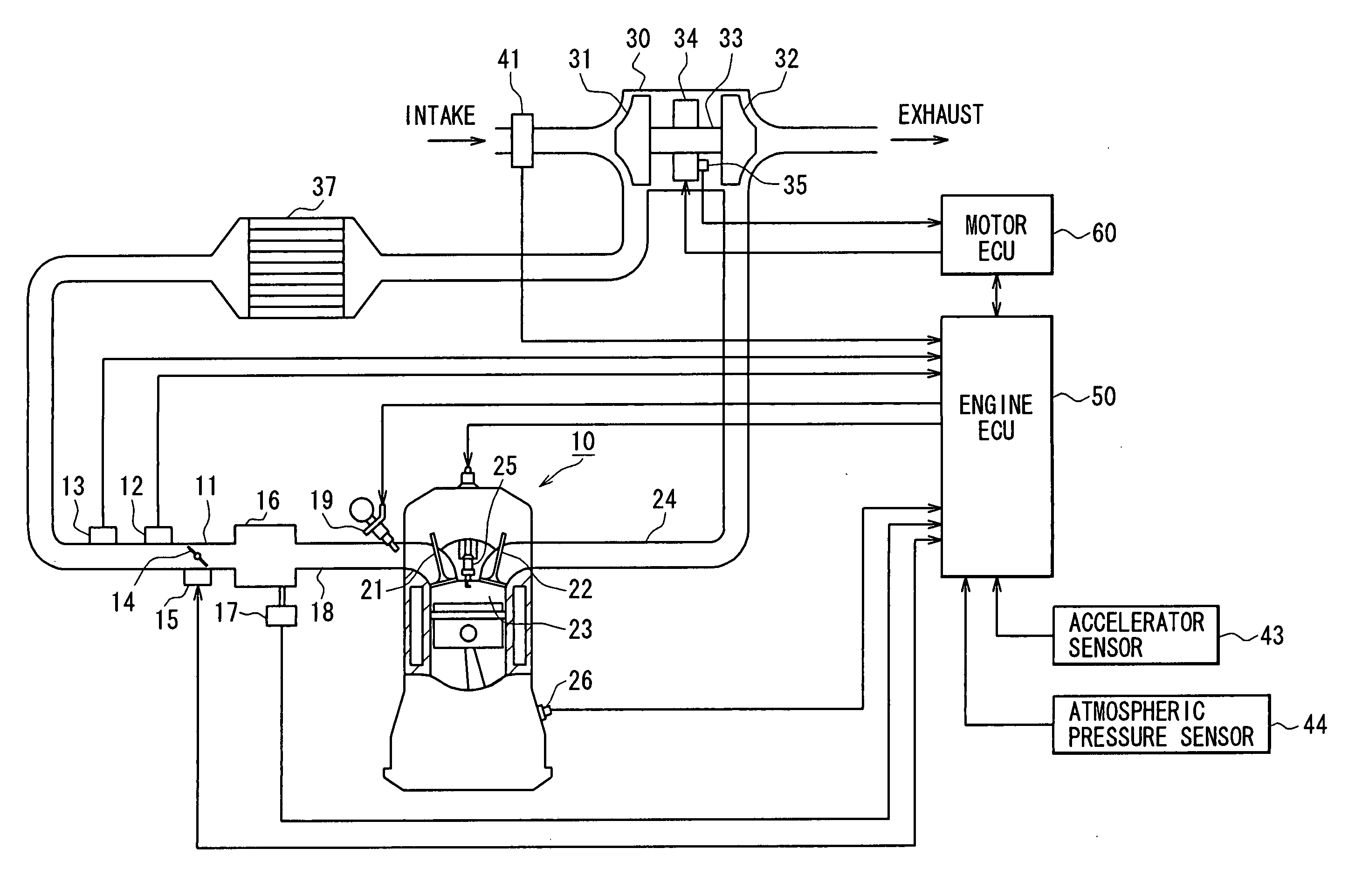
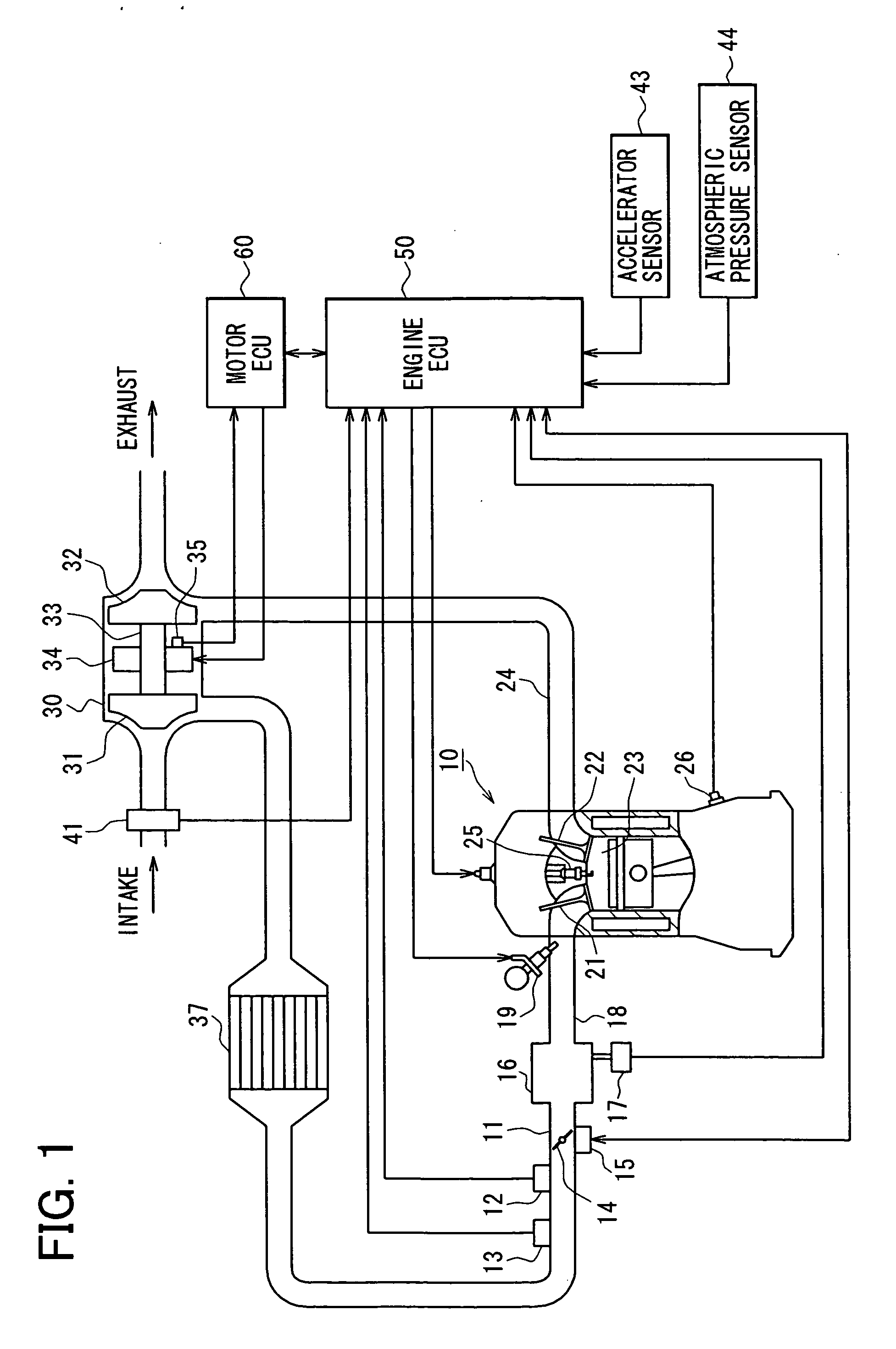
[0047] An embodiment of the present invention will be described below with reference to the drawings. In the embodiment, an engine control system is constructed for an on-vehicle multi-cylinder gasoline engine as an internal combustion engine, and the engine of the control system is provided with an electrically-assisted turbocharger (hereinbelow, also called electric turbocharger) as a supercharger. First, a general schematic configuration diagram of an engine control system will be described with reference to FIG. 1.

[0048] In an engine 10 shown in FIG. 1, an intake pipe 11 is provided with a throttle valve 14 as air amount adjusting means whose position is adjusted by a throttle actuator 15 such as a DC motor or the like. The throttle actuator 15 has therein a throttle position sensor for detecting the throttle position. On the upstream side of the throttle valve 14, a boost pressure sensor 12 for detecting pressure on the throttle upstream side (boost pressure generated by a tur...

second embodiment

[0128]FIG. 18 is a general schematic configuration diagram of an engine control system. The same reference numerals are designated to the same components as those of the first embodiment and the description will not be repeated. The description of the same operations will not be also repeated.

[0129] In the intake pipe 11, an auxiliary electric compressor 38 is provided on the compressor upstream side of the turbocharger 30. By the auxiliary compressor 38, the intake air is compressed on the upstream side of the turbocharger 30. The auxiliary compressor 38 uses a motor 38a as a drive source. When the motor 38a is driven by power supply from a battery (not shown), the auxiliary compressor 38 operates. That is, different from the turbocharger 30, the auxiliary compressor 38 uses power other than exhaust as its power source.

[0130] The engine ECU 50 determines a control amount of the auxiliary compressor 38 (motor 38a) interlockingly with the torque base control. Consequently, when the...

third embodiment

[0174]FIG. 30 is a general schematic configuration diagram of an engine control system.

[0175] In an engine 210 shown in FIG. 30, a piston 212 is housed in a cylinder block 211, and a combustion chamber 214 is defined by the cylinder inner walls, the piston 212, and a cylinder head 213. In the cylinder head 213, an electrically-controlled fuel injection valve 215 is disposed. A high-pressure fuel is supplied from a common rail 216 to the fuel injection valve 215, and the fuel is injected into the combustion chamber 214 by an opening operation of the fuel injection valve 215. Although not shown, the system has a fuel pump for pressure-feeding the fuel in a fuel tank to the common rail 216. Afuel discharge amount of the fuel pump is controlled on the basis of a pressure (fuel pressure) in the common rail detected by a sensor or the like.

[0176] An intake valve 217 is disposed for an intake port, and an exhaust valve 218 is disposed for an exhaust port. An exhaust pipe 221 is connected...


PUM


Abstract

A torque base control unit calculates target torque based on an accelerator position and engine speed. The control unit further executes calculation of target airflow rate, calculation of target intake pressure, and calculation of target boost pressure based on the target torque. Target throttle position is calculated based on the target airflow rate, target intake pressure, target boost pressure, actual boost pressure, and throttle passed intake temperature. An assist control unit calculates target turbine power based on the target airflow rate and the target boost pressure calculated by the torque base control unit and calculates actual turbine power based on exhaust information. Assist power of a motor attached to a turbocharger is calculated based on the power difference between the target turbine power and the actual turbine power.

Description

CROSS-REFERENCE TO RELATED APPLICATION [0001] This application is based on Japanese Patent Applications No. 2005-57568 field on Mar. 2, 2005, No. 2005-57569 filed on Mar. 2, 2005, and No. 2005-57570 filed on Mar. 2, 2005, the disclosure of which is incorporated herein by reference. FIELD OF THE INVENTION [0002] The present invention relates to a controller applied to an internal combustion engine having a supercharger such as a turbocharger, the controller suitably controlling assist power to the supercharger. BACKGROUND OF THE INVENTION [0003] As a supercharger for supercharging intake air by using exhaust power, a turbocharger is generally known. In recent years, an electrically-assisted turbocharger is developed in which an electric motor or the like is attached to the rotary shaft of the turbocharger and which assists exhaust power in accordance with an operating state of an internal combustion engine. [0004] A controller disclosed in JP-11-117933A controls current passed to an ...

Claims


Application Information

Patent Timeline
Patent Type & Authority Applications(United States)
IPC IPC(8): F02B33/44
CPCF02B33/44F02B37/10F02B37/14F02D41/0007F02D2041/1433F02D2200/0406Y02T10/144Y02T10/12F02B37/12F02D23/00
Inventor KIMOTO, KAYOKOISOBE, DAIJI
Owner DENSO CORP
Why Eureka
Try Eureka