Turbocharged engine cylinder head internal cooling

a technology for engine cylinders and internal cooling, which is applied in the direction of cylinders, machines/engines, mechanical equipment, etc., can solve the problems of adding cost to the engine/turbocharger assembly, and achieve the effect of lowering the operating temperature of the cylinder head

Inactive Publication Date: 2009-05-21
GM GLOBAL TECH OPERATIONS LLC
View PDF3 Cites 76 Cited by
  • Summary
  • Abstract
  • Description
  • Claims
  • Application Information

AI Technical Summary

Benefits of technology

[0003]The present invention provides an engine cylinder head with an exhaust manifold integrally cast as part of the cylinder head casting. The turbocharger with its turbine body is mounted directly to an exhaust outlet of the internal exhaust manifold in the cylinder head. A dual level water jacket within the cylinder head is provided with separate coolant feeds for the upper and lower cooling jackets. The cooling jackets extend above and below the exhaust outlet and are connected inward of the exhaust mounting face to reduce metal temperatures of the mounting face below those of the associated turbocharger exhaust inlet flange.
[0004]Separate cores for the upper and lower jackets are connected at coolant inlet and outlet locations at opposite ends. Intermediate core print connectors form controlled flow passages between the upper and lower jackets at critical areas near the combustion chambers and exhaust ports in the cylinder head and integrated manifold. The improved cooling in these areas lowers operating temperatures in the cylinder head and obviates the need for a separate exhaust manifold.

Problems solved by technology

However, the separate exhaust manifold occupies additional space in the automobile engine compartment and adds cost to the engine / turbocharger assembly.

Method used


Image

  • Turbocharged engine cylinder head internal cooling
  • Turbocharged engine cylinder head internal cooling
  • Turbocharged engine cylinder head internal cooling

Examples


Embodiment Construction

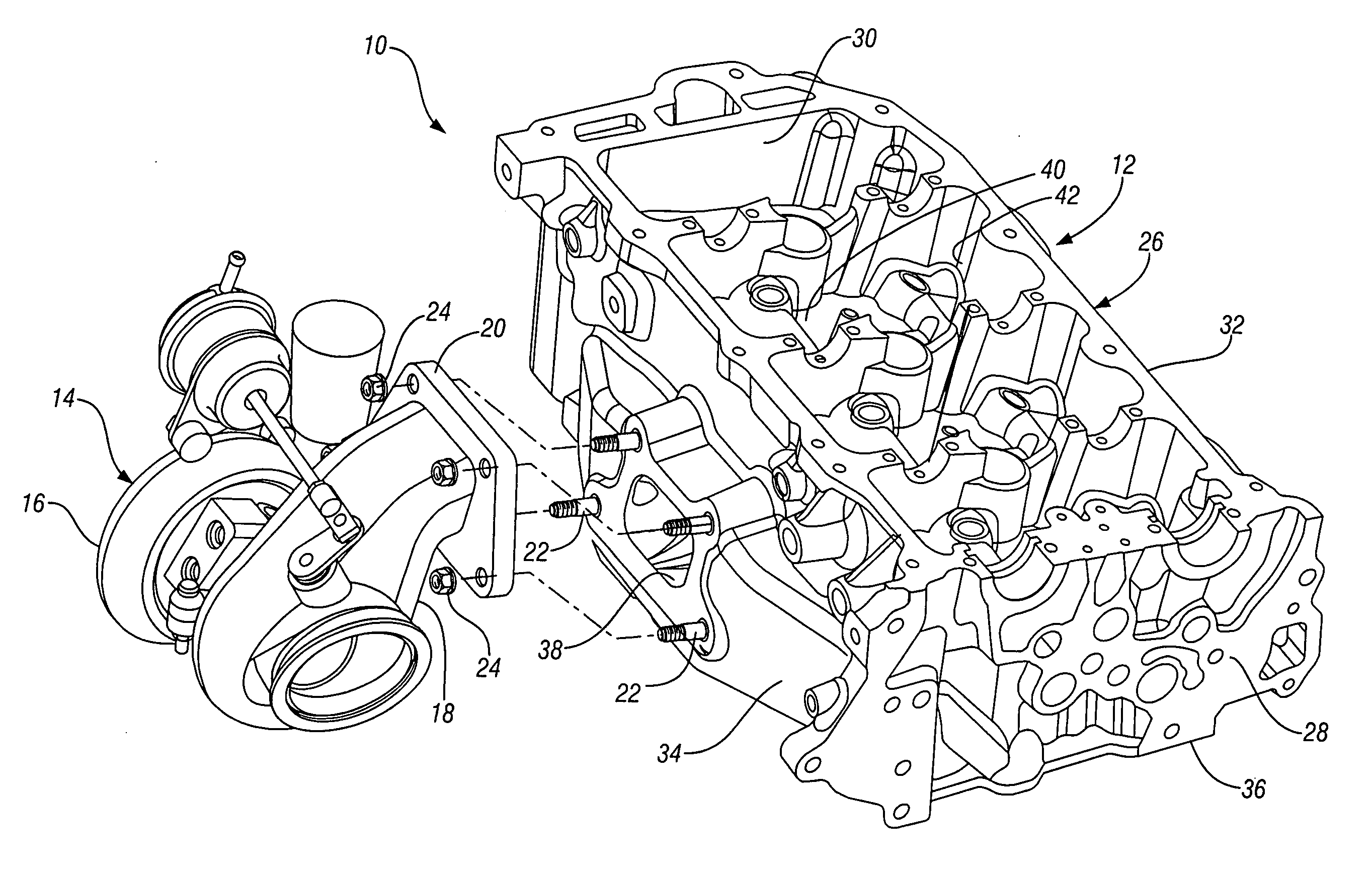
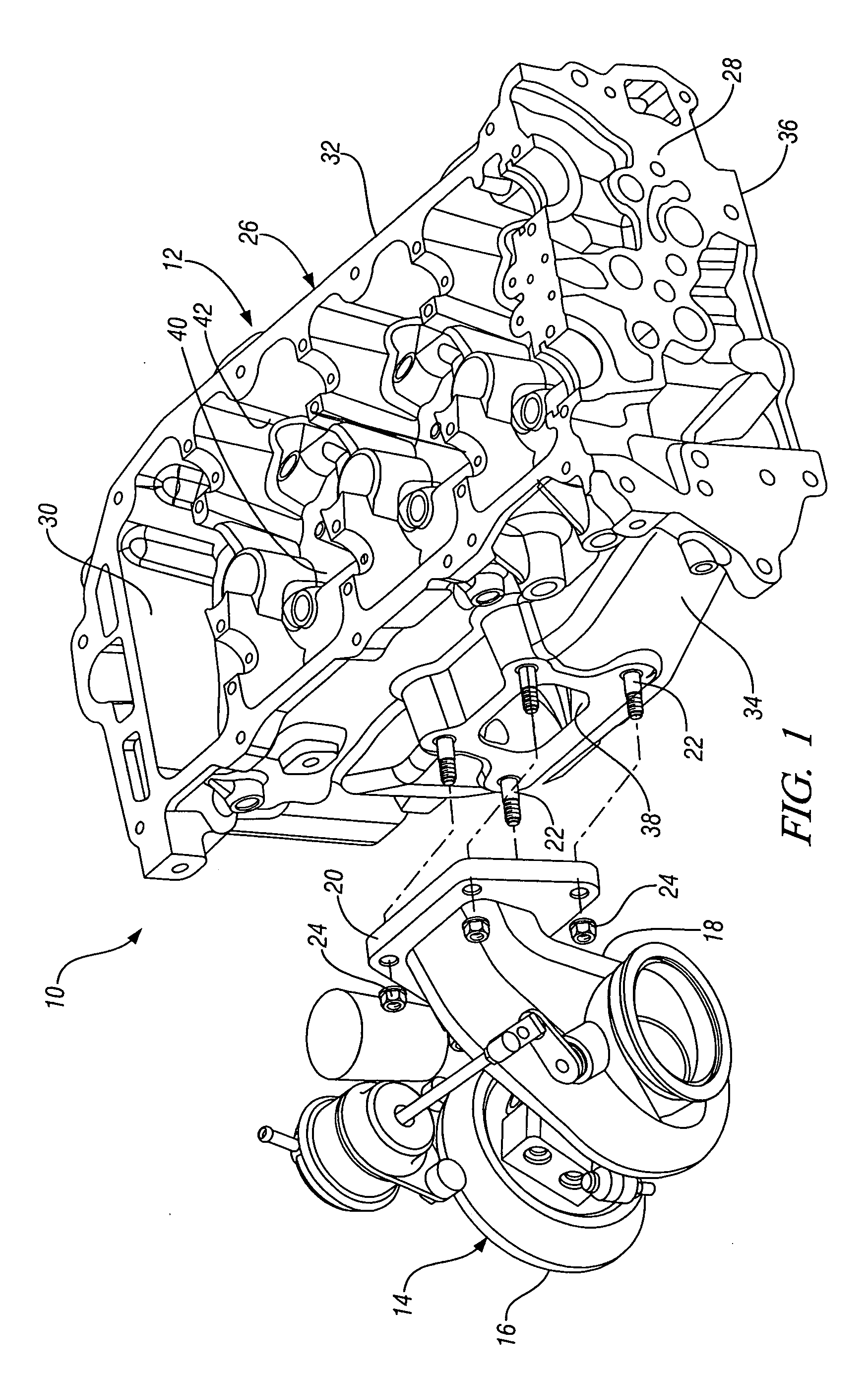
[0020]Referring first to FIGS. 1-5 of the drawings in detail, numeral 10 generally indicates an exploded assembly of an engine cylinder head 12 and an engine turbocharger 14. The turbocharger is of generally conventional design adapted for mounting directly to the cylinder head 12. The turbocharger includes a compressor section 16 having a compressor wheel, not shown, driven by a turbine wheel, not shown, carried in a turbine section enclosed by a housing 18 of material including, but not limited to, stainless steel or other suitable material. The housing includes a turbine inlet flange 20 mounted on the engine cylinder head by fasteners, including, but not limited to, threaded studs 22 and nuts 24.

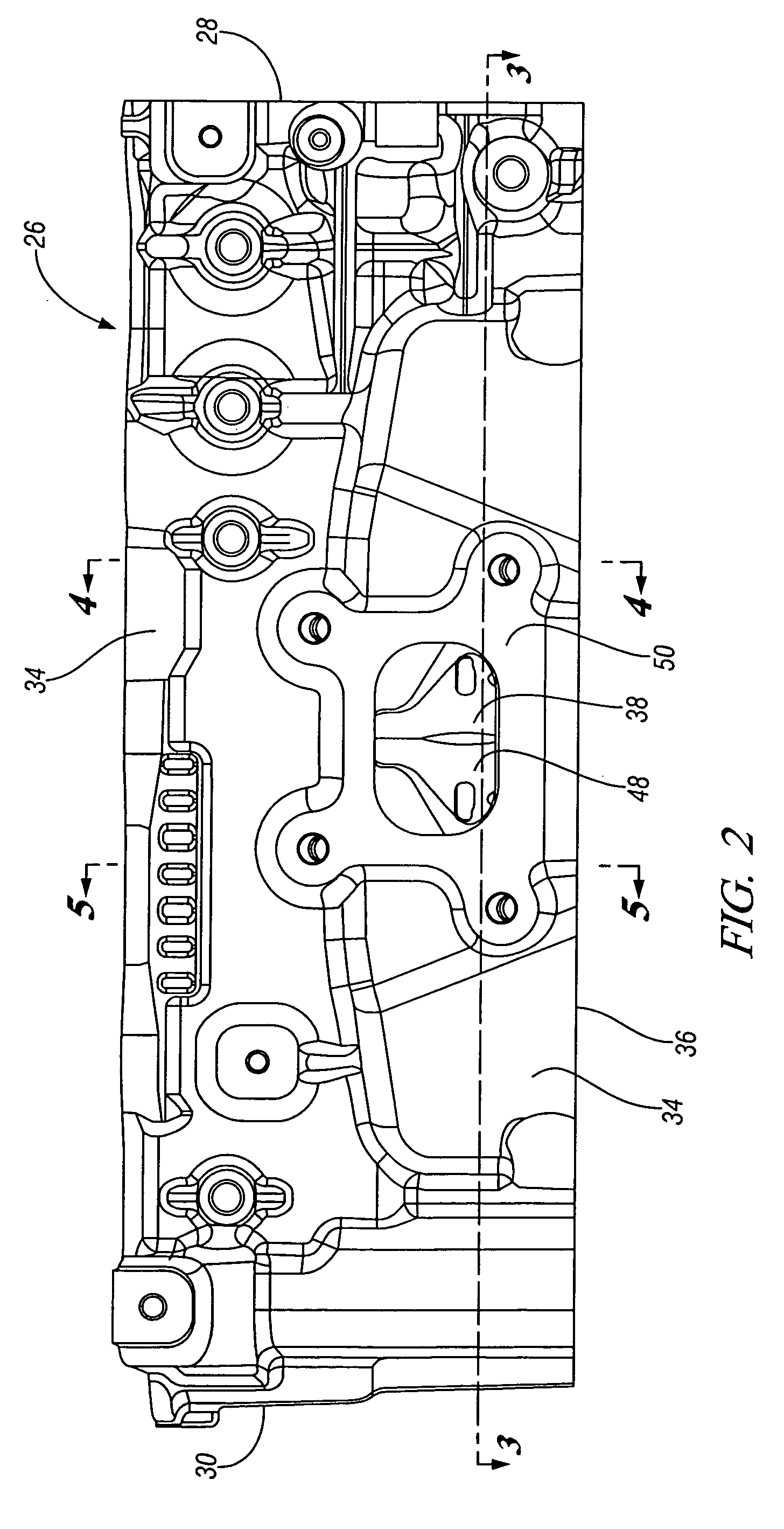
[0021]The cylinder head 12 is represented in FIG. 1 by a machined casting 26 of suitable material including, but not limited to, aluminum based alloys. Other components of an assembled cylinder head, such as camshaft covers camshaft drive cover, camshafts, drive mechanisms, engine valves ...


PUM


Abstract

An engine cylinder head has an exhaust manifold cast in the cylinder head. A turbocharger with a turbine body is adapted to mount directly to an exhaust outlet mounting face of the exhaust manifold. A dual level water jacket within the cylinder head has separate coolant feeds for upper and lower cooling jackets. The cooling jackets extend above and below the exhaust outlet and are connected inward of the exhaust mounting face to reduce metal temperatures of the mounting face below those of the turbocharger exhaust inlet flange. Separate cores for the upper and lower jackets are connected at coolant inlet and outlet locations at opposite ends. Intermediate core print connectors form controlled flow passages between the upper and lower jackets and exhaust ports in the cylinder head and integrated manifold. The improved cooling in these areas lowers operating temperatures in the cylinder head and obviates the need for a separate exhaust manifold.

Description

TECHNICAL FIELD[0001]This invention relates to an engine cylinder head with internal exhaust manifold and dual level cooling passages to minimize heat conduction from a directly attached turbocharger.BACKGROUND OF THE INVENTION[0002]It is known in the art relating to turbocharged automotive engines to utilize an exhaust manifold between the cylinder head and the turbocharger to minimize the conduction of heat from the exhaust turbine back to the engine cylinder head. However, the separate exhaust manifold occupies additional space in the automobile engine compartment and adds cost to the engine / turbocharger assembly.SUMMARY OF THE INVENTION[0003]The present invention provides an engine cylinder head with an exhaust manifold integrally cast as part of the cylinder head casting. The turbocharger with its turbine body is mounted directly to an exhaust outlet of the internal exhaust manifold in the cylinder head. A dual level water jacket within the cylinder head is provided with separa...

Claims


Application Information

Patent Timeline
Patent Type & Authority Applications(United States)
IPC IPC(8): F02F1/10
CPCF01N3/046F02B67/10Y02T10/20F02F1/40F02F1/243Y02T10/12
Inventor LESTER, DOMINIQUE T.OSTROWSKI, DOUGLAS
Owner GM GLOBAL TECH OPERATIONS LLC
Why Eureka
Try Eureka