A gas turbine guide leading edge mounting edge structure and a gas turbine having the same

A gas turbine and guider technology, which is applied in the direction of gas turbine devices, cooling of turbine/propulsion devices, machines/engines, etc., can solve problems such as increasing cooling air flow, unfavorable engine performance, etc., to reduce gas temperature, improve cooling effect, The effect of reducing thermal stress

Active Publication Date: 2019-02-15
INST OF ENGINEERING THERMOPHYSICS - CHINESE ACAD OF SCI
View PDF6 Cites 0 Cited by
  • Summary
  • Abstract
  • Description
  • Claims
  • Application Information

AI Technical Summary

Problems solved by technology

But this approach is bound to greatly increase the cooling air flow, which is extremely detrimental to the performance of the engine

Method used


Image

  • A gas turbine guide leading edge mounting edge structure and a gas turbine having the same
  • A gas turbine guide leading edge mounting edge structure and a gas turbine having the same

Examples


Embodiment Construction

[0033] In order to make the purpose, technical solutions and advantages of the present invention clearer, the invention will be further described in detail below in conjunction with specific examples. The following examples are explanations of the present invention, and the present invention is not limited to the following examples.

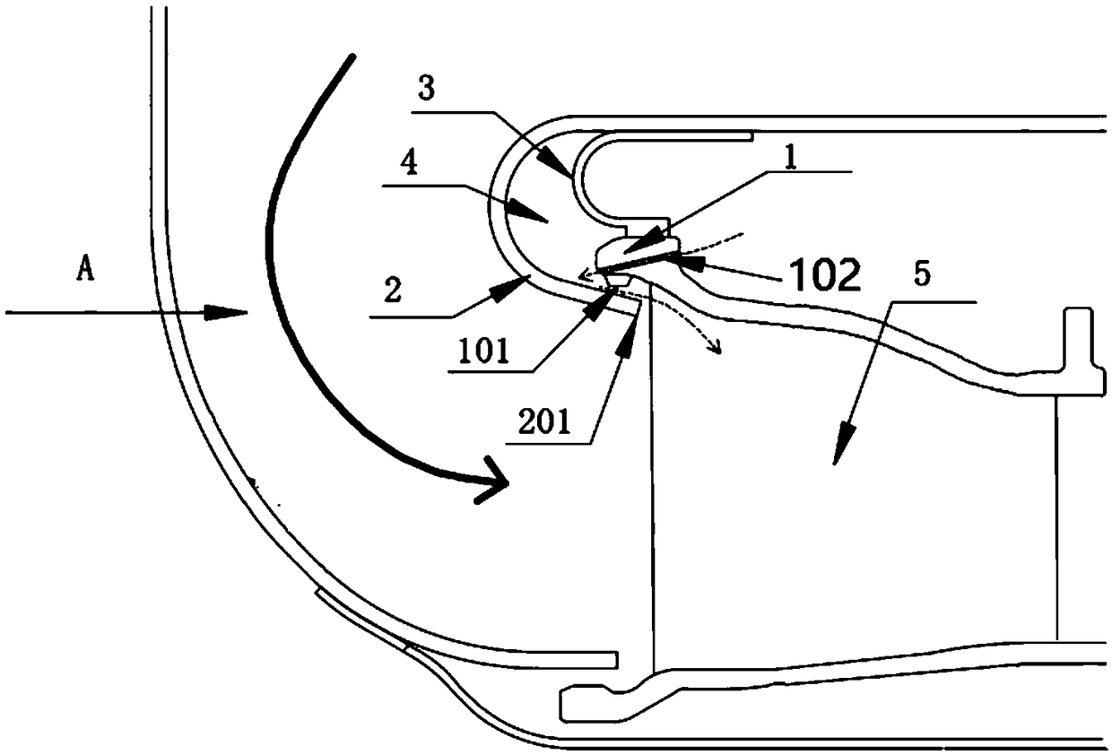
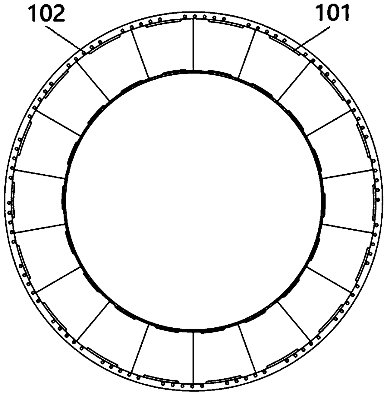
[0034] Such as figure 1 , 2 As shown, in the gas turbine guider leading edge mounting edge structure of the present invention, 1 is the gas turbine guider leading edge mounting edge, 2 is the end wall of the outlet of the combustion chamber, 3 is the auxiliary annular bent plate, and 4 is the annular cooling chamber , 5 is the gas turbine guide. The front edge mounting edge 1 of the gas turbine guide is arranged downstream of the outlet of the combustion chamber, and the front edge installation edge 1 of the gas turbine guide overlaps the end wall surface 2 of the outlet of the combustion chamber. The front edge mounting edge 1 of the gas turbi...


PUM


Abstract

The invention provides a gas turbine guider front edge mounting side structure and a gas turbine with the structure. Multiple bosses are arranged on the inner side of a turbine guider front edge mounting side, the bosses are located on the side, close to the force suction face, of the turbine guider blade channel front edge, the gas turbine guider front edge mounting side is in lap joint to the outer side wall face of a combustion chamber outlet portion tail end through the bosses, an auxiliary annular bending plate is in lap joint with the outer side wall face of the turbine guider front edge mounting side, an annular cooling cavity is defined by the annular bending plate, the outer side wall face of the combustion chamber outlet portion and the turbine guider front edge mounting side; multiple airflow holes are formed in the turbine guider front edge mounting side in the circumferential direction of the turbine guider front edge mounting side, the outer sides of the airflow holes are communicated with cooling gas of an air system, and the inner sides of the airflow holes are communicated with the annular cooling cavity. According to the above structure, a secondary air system flow path is optimized, the cooling effect of the gas turbine guider inner and outer ring gas side end wall is improved, and the use amount of cooling air is reduced.

Description

technical field [0001] The present invention relates to the turbine field of high-temperature components of gas turbines, and more specifically, relates to a new type of gas turbine guider leading edge mounting edge structure, which is used to change the flow path of the secondary air system, and the cooling air flow can be used in a more effective way, thereby Achieve higher cooling efficiency and less cold air flow, improving overall engine performance. Background technique [0002] In order to improve the performance of the gas turbine, the temperature before the high pressure turbine is continuously increased. The turbine inlet gas temperature of advanced aviation turbofan engines has reached 1800K-2050K, far exceeding the allowable temperature of existing superalloys. In order to ensure the safe operation of the high-pressure turbine, effective cooling must be implemented to reduce the metal wall temperature of the high-pressure turbine guide. [0003] When designing ...

Claims


Application Information

Patent Timeline
Patent Type & Authority Patents(China)
IPC IPC(8): F01D9/04F01D25/12F02C3/14F02C7/18
CPCF01D9/023F01D9/042F02C3/14F02C7/18F05D2260/201F05D2260/202
Inventor 徐庆宗刘军杜强王沛柳光刘红蕊杨晓洁高金海胡嘉麟
Owner INST OF ENGINEERING THERMOPHYSICS - CHINESE ACAD OF SCI
Why Eureka
Try Eureka