Turbine guide vane and gas turbine engine

A turbine guide vane and fuel technology, which is applied to engine components, machines/engines, turbines/propellant fuel delivery systems, etc., to achieve the effects of increasing output power, reducing metal temperature, and improving power-to-weight ratio

Active Publication Date: 2021-08-03
AECC HUNAN AVIATION POWERPLANT RES INST
View PDF5 Cites 0 Cited by
  • Summary
  • Abstract
  • Description
  • Claims
  • Application Information

AI Technical Summary

Problems solved by technology

[0004] The invention provides a turbine guide vane and a gas turbine engine to solve the technical problem that the existing gas turbine engine still needs to increase the energy added by fuel combustion to increase the power-to-weight ratio

Method used


Image

  • Turbine guide vane and gas turbine engine
  • Turbine guide vane and gas turbine engine
  • Turbine guide vane and gas turbine engine

Examples


Embodiment Construction

[0024] The embodiments of the present invention will be described in detail below with reference to the accompanying drawings, but the present invention can be implemented in various ways defined and covered below.

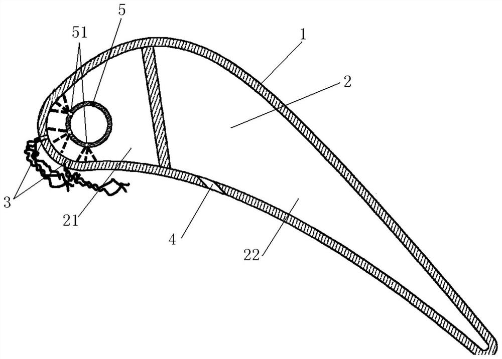
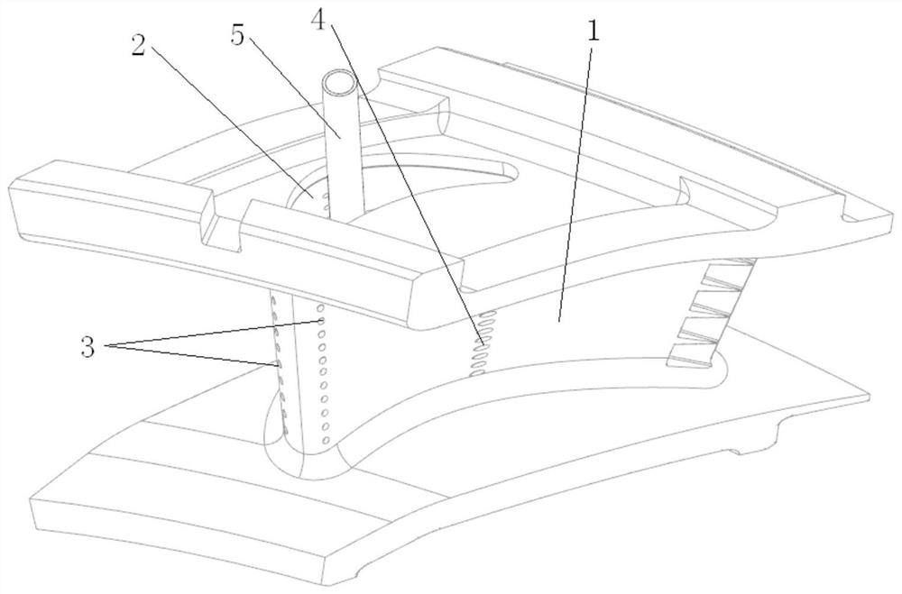
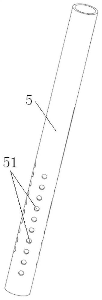
[0025] figure 1 is a schematic cross-sectional structure diagram of a turbine guide vane in a preferred embodiment of the present invention; figure 2 is a schematic structural view of a turbine guide vane in a preferred embodiment of the present invention; image 3 It is a structural schematic diagram of a fuel injection rod in a preferred embodiment of the present invention.

[0026] Such as figure 1 and figure 2 As shown, the turbine guide vane 1 of the present embodiment is provided with a cooling cavity 2 in the turbine guide vane 1, and the turbine guide vane 1 includes a leading edge, a trailing edge, a pressure surface and a suction surface, and a cooling cavity 2 is provided on the turbine guide vane 1. The premixed gas injection hole 3 connected to ...


PUM


Abstract

The invention discloses a turbine guide vane and a gas turbine engine. A cooling cavity is arranged in the turbine guide vane; the turbine guide vane comprises a front edge, a tail edge, a pressure surface and a suction surface; premixed gas injection holes communicating with the cooling cavity are formed in the turbine guide vane; and fuel is injected to the inner wall face of the cooling cavity from the cooling cavity, so that the fuel absorbs heat and is gasified on the inner wall face of the cooling cavity and then mixed with cold air in the cooling cavity to form premixed gas, and the premixed gas is injected to high-temperature high-pressure fuel gas around the turbine guide vane via the premixed gas injection holes to be combusted. According to the turbine guide vane, the energy added by the fuel combustion is increased through the supplementary combustion in the turbine guide vane, so that the temperature margin of a subsequent stage of turbine is fully utilized, the output power of the whole machine is greatly increased, and the power-to-weight ratio of the gas turbine engine is increased.

Description

technical field [0001] The invention relates to the technical field of gas turbine engines, in particular to a turbine guide vane and a gas turbine engine. Background technique [0002] Aviation gas turbine engines usually consist of compressors, combustors, and turbines. Its working principle is that after the air is compressed by the compressor, the pressure increases, the temperature rises, and it flows into the combustion chamber. The high-pressure air is mixed and burned with the injected fuel in the combustion chamber to form high-temperature and high-pressure gas, and the temperature is greatly increased, which increases the heat energy contained in the gas. The high-temperature and high-pressure gas flows into the turbine, and the power extraction is realized in the turbine to drive the compressor, and the remaining energy is used to output shaft power or generate thrust. The gas is finally exhausted into the atmosphere. [0003] Aeroengine power-to-weight ratio (...

Claims


Application Information

Patent Timeline
Patent Type & Authority Applications(China)
IPC IPC(8): F01D9/02F01D25/12F02C7/224
CPCF01D9/02F01D25/12F02C7/224
Inventor 张绍文李维陈竞炜
Owner AECC HUNAN AVIATION POWERPLANT RES INST
Why Eureka
Try Eureka