Pressure-charged internal combustion engine

a technology of internal combustion engine and pressure-charged engine, which is applied in the direction of engines, machines/engines, mechanical equipment, etc., can solve the problems of reducing efficiency, affecting efficiency, and reducing power provided, so as to improve emission behavior and improve emission characteristics

Inactive Publication Date: 2006-03-23
FORD GLOBAL TECH LLC
View PDF8 Cites 76 Cited by
  • Summary
  • Abstract
  • Description
  • Claims
  • Application Information

AI Technical Summary

Benefits of technology

[0025] An advantage of the present invention is that it provides better emission characteristics during the warm-up period.
[0026] The first partial object is achieved by a pressure-charged internal combustion engine having an intake line for supplying fresh air and an exhaust-gas line for discharging the exhaust gas and at least two exhaust-gas turbochargers which are connected in series and which each comprise a turbine arranged in the exhaust-gas line and a compressor arranged in the intake line and of which a first exhaust-gas turbocharger serves as high-pressure stage and a second exhaust-gas turbocharger arranged downstream of the exhaust-gas line and upstream of the intake line of the first exhaust-gas turbocharger serves as low-pressure stage, an exhaust-gas aftertreatment system being provided downstream of the turbine of the second exhaust-gas turbocharger, and a second exhaust-gas treatment system of the same type being additionally provided, wherein the second exhaust-gas aftertreatment system is arranged in the exhaust-gas line between the two turbines of the at least two exhaust-gas turbochargers.
[0027] The internal combustion engine according to the invention is equipped with a second exhaust-gas aftertreatment system which is of the same type as the firs

Problems solved by technology

Whereas a mechanical charger draws the energy required for its drive entirely from the mechanical energy provided at the crankshaft by the internal combustion engine and thus reduces the power provided and in this way adversely affects the efficiency, the exhaust-gas turbocharger uses the energy of the hot exhaust gases produced by the internal combustion engine.
Here, too, a reduction in the efficiency may occur, since the exhaust-gas counterpressure is increased compared with the naturally aspirated engine.
On the other hand, however, the hot exhaust gases are to cover as short a distance as possible to the various exhaust-gas aftertreatment systems so that these exhaust gases have little time to cool down and the exhaust-gas aftertreatment systems reach their operating temperature or light-off temperature as quickly as possible.
A disadvantage with the concept proposed in EP 1 396 619 A1 is that either the exhaust-gas flow, with regard to a good emission behavior, is fed directly to an exhaust-gas aftertreatment means, in the course of which the internal combustion engine is not pressure-charged as a res

Method used


Image

  • Pressure-charged internal combustion engine
  • Pressure-charged internal combustion engine
  • Pressure-charged internal combustion engine

Examples


first embodiment

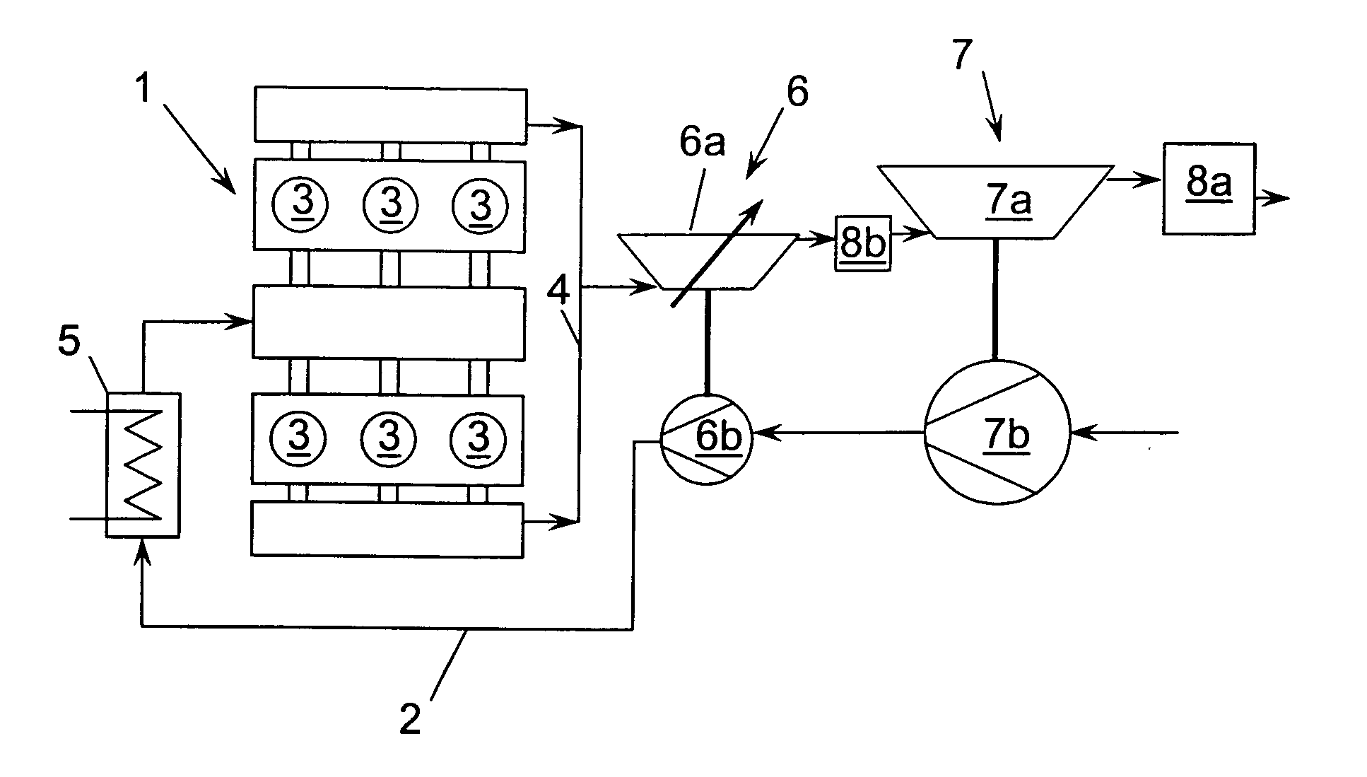
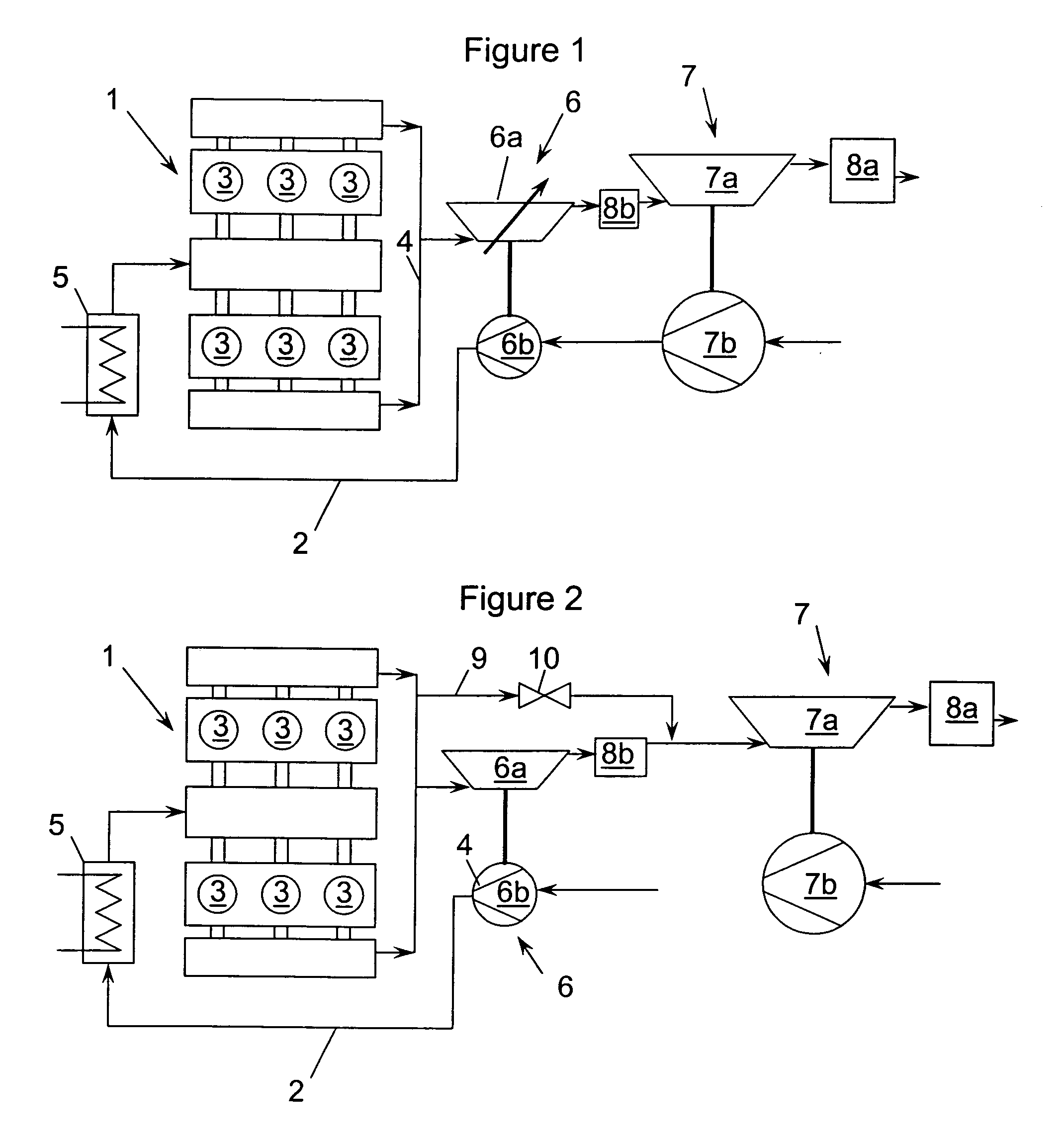
[0068]FIG. 1 shows a pressure-charged internal combustion engine 1, taking a six-cylinder V engine as an example.

[0069] The internal combustion engine 1 has an intake line 2 which supplies the cylinders 3 with fresh air and also an exhaust-gas line 4 which serves to discharge the combustion gases or the exhaust gas. Furthermore, the internal combustion engine 1 is equipped with two exhaust-gas turbochargers 6, 7 which are connected in series, so that, on the one hand, the exhaust-gas flow flows through two turbines 6a, 7a arranged one behind the other in the exhaust-gas line 4, whereas the charge-air flow is passed through to compressors 6b, 7b arranged one behind the other in the intake line 2. A first exhaust-gas turbocharger 6 arranged close to the exhaust of the internal combustion engine 1 serves as high-pressure stage 6. A second exhaust-gas turbocharger 7 arranged downstream of the exhaust-gas line 4 or upstream of the intake line 2 of the first exhaust-gas turbocharger 6 ser...

second embodiment

[0074]FIG. 2 schematically shows the pressure-charged internal combustion engine 1. Only the differences from the embodiment shown in FIG. 1 are to be discussed, for which reason reference is otherwise made to FIG. 1. The same designations have been used for the same components.

[0075] In contrast to the embodiment shown in FIG. 1, the high-pressure turbine 6a in the internal combustion engine 1 shown in FIG. 2 is designed with a fixed, i.e., invariable, turbine geometry. In addition, a first bypass line 9 is provided, which branches off from the exhaust-gas line 4 upstream of the turbine 6a of the first exhaust-gas turbocharger 6 and opens into the exhaust-gas line 4 again downstream of the second exhaust-gas aftertreatment system 8b, a valve 10 being arranged in this first bypass line 9.

[0076] The bypass line 9 serves as an exhaust-gas bleed line. The high-pressure turbine 6a is thus designed in a similar manner to a wastegate turbine, it being possible for the second exhaust-gas ...

fourth embodiment

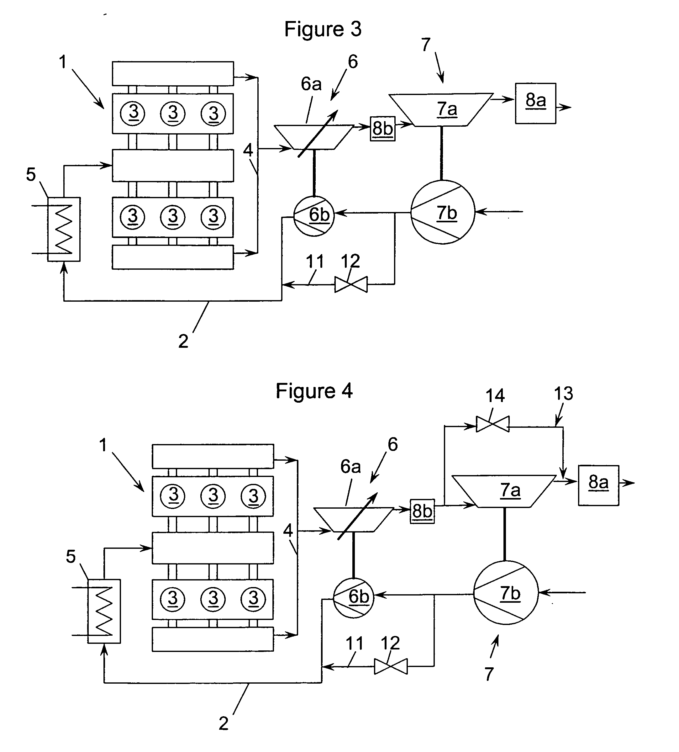
[0080]FIG. 4 schematically shows the pressure-charged internal combustion engine 1. In contrast to the embodiment shown in FIG. 3, a third bypass line 13 is provided for the purposes of exhaust-gas bleeding, this third bypass line 13 branching off from the exhaust-gas line 4 upstream of the turbine 7a of the second exhaust-gas turbocharger 7 and opening into the exhaust-gas line 4 again upstream of the first exhaust-gas aftertreatment system 8a, it being possible for the turbine 7a of the second exhaust-gas turbocharger 7 to be bypassed by this second bypass line 13, a valve 14 being provided in the third bypass line 13 for controlling the exhaust-gas bleeding. The low-pressure turbine 7a is thus designed in the form of a wastegate turbine.


PUM


Abstract

The invention relates to a system and method for improving the emission characteristics of a pressure-charged internal combustion engine. The engine (1) has an intake line (2) and an exhaust-gas line (4) and at least two exhaust-gas turbochargers (6, 7) connected in series. Each turbocharger has a turbine (6a, 7a) in the exhaust-gas line (4) and a compressor (6b, 7b) in the intake line (2). The first exhaust-gas turbocharger (6) serves as high-pressure stage (6). The second exhaust-gas turbocharger (7) serves as low-pressure stage (7). Two exhaust-gas aftertreatment systems are located in between and after the turbines.

Description

FIELD OF THE INVENTION [0001] The invention relates to a system and method for improving the emission characteristics of a pressure-charged internal combustion engine. BACKGROUND AND SUMMARY OF THE INVENTION [0002] In recent years, there has been a development toward small, highly pressure-charged engines, the pressure-charging primarily being a method of increasing the power in which the air required for the engine combustion process is compressed. The economic importance of these engines for the automotive industry is steadily increasing. [0003] As a rule, an exhaust-gas turbocharger, in which a compressor and a turbine are arranged on the same shaft, is used for the pressure-charging, the hot exhaust-gas flow being fed to the turbine and expanding in this turbine while delivering energy, as a result of which the shaft is set in rotation. The energy delivered by the exhaust-gas flow to the turbine and finally to the shaft is used for driving the compressor, likewise arranged on th...

Claims


Application Information

Patent Timeline
IPC IPC(8): F01N5/04F02B33/44
CPCF01N3/101F01N13/009F01N13/107F01N2240/36F01N2340/02F01N2340/06F02B29/0406F02B37/013F02B37/127F02B37/16F02B37/18F02B37/22Y02T10/144Y02T10/22F01N13/0093F01N3/2006F02B37/162Y02T10/12
Inventor SPAEDER, UWE R.SCHORN, NORBERT A.KINDL, HELMUT M.
Owner FORD GLOBAL TECH LLC
Why Eureka
Try Eureka