

Plasma display device
a technology of plasma display device and plasma, which is applied in the direction of luminescent compositions, chemistry apparatus and processes, gas-filled discharge tubes, etc., can solve the problems of phosphors not being suitable for fabricating high-quality plasma display devices, degrading color purity,
- Summary
- Abstract
- Description
- Claims
- Application Information
AI Technical Summary
Benefits of technology
Problems solved by technology
Method used
Image

Examples
embodiment 1
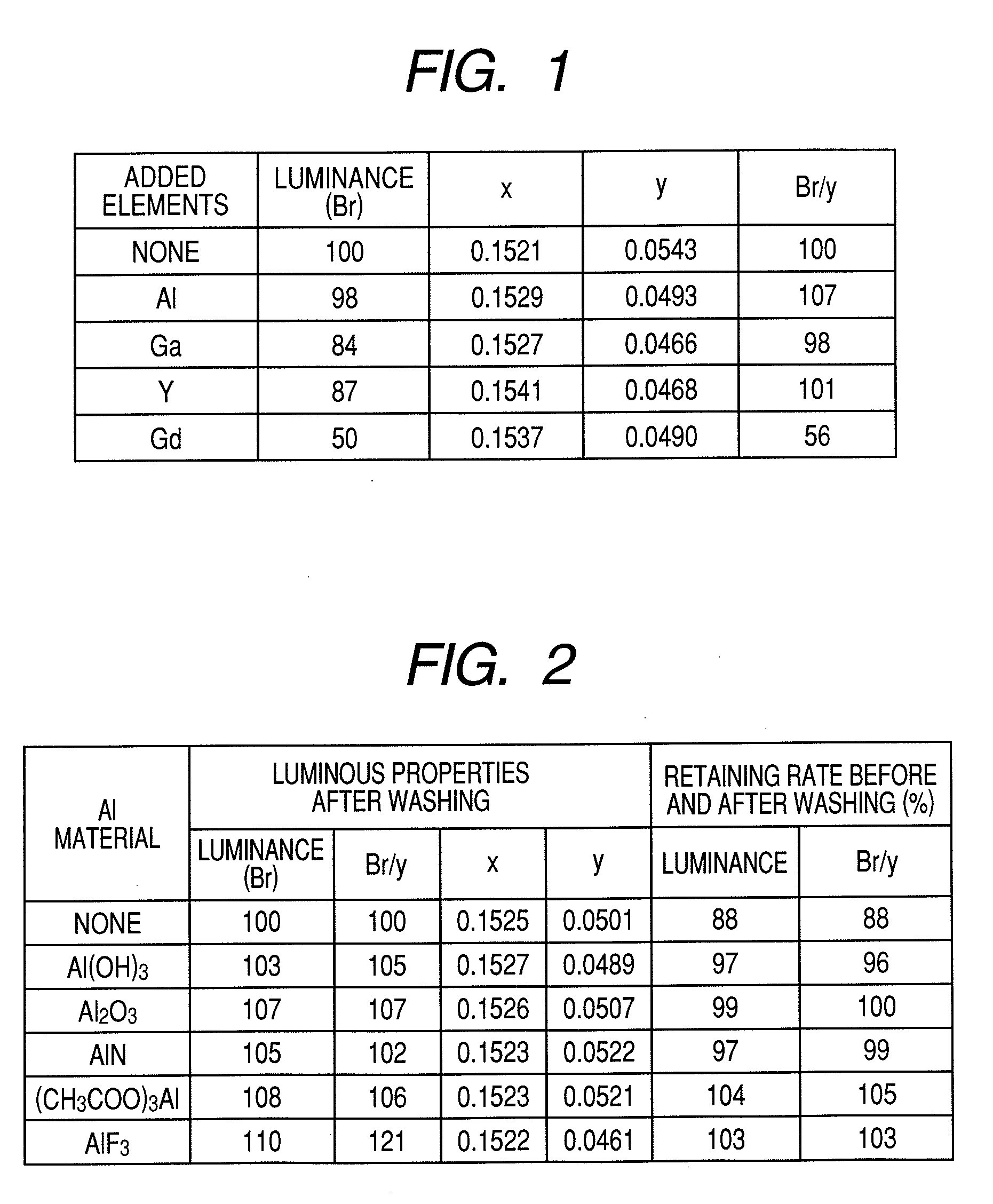
[0077]To fabricate a plasma display panel as a first embodiment of the present invention, the inventors first synthesized an Eu activated silicate phosphor as an essential constituent element of the present invention. The first phosphor being synthesized was obtained by adding 0.03 mol of Al to (Ba0.25Sr0.75)2.93MgSi2O8:Eu0.07.
[0078]For the synthesis of a phosphor, SrCO3, BaCO3, MgCO3, SiO2, EuPO4, and Al(OH)3 were weighed to have a mole ratio of Sr:Ba:Mg:Si:Eu:Al at 2.197 (3.243 g):0.733 (1.446 g):1.0 (0.959 g):2.0 (1.202 g):0.07 (0.173 g):0.03 (0.023 g). Then, 0.30 mol of NH4Cl as a flux was added with respect to 1 mol of the phosphor, and fully mixed with the other material powders in an agate mortar.
[0079]Thereafter, the obtained mixture was filled into a heat-stable vessel and heated first for 2 hours at 600° C. in the atmosphere and then for 3 hours at 1200° C. in a reducing atmosphere. The obtained product was then pulverized, washed with water and dried so as to obtain a sil...
embodiment 2
[0091]To fabricate a plasma display panel as the first embodiment of the present invention, the inventors first synthesized an Eu activated silicate phosphor as an essential constituent element of the present invention.
[0092]The first phosphor being synthesized was obtained by adding 0.03 mol of Al(OH)3 as a starting material to (Ba0.25Sr0.75)2.93MgSi2O8:Eu0.07.
[0093]For the synthesis of a phosphor, SrCO3, BaCO3, MgCO3, SiO2, EuPO4, and Al(OH)3 were weighed to have a mole ratio of Sr:Ba:Mg:Si:Eu:Al at 2.197 (3.243 g):0.733 (1.446 g):1.0 (0.959 g):2.0 (1.202 g):0.07 (0.173 g):0.03 (0.023 g). Then, 0.30 mol of NH4Cl as a flux was added with respect to 1 mol of the phosphor, and fully mixed with the other material powders in an agate mortar.
[0094]Thereafter, the obtained mixture was filled into a heat-stable vessel and heated first for 2 hours at 600° C. in the atmosphere and then for 3 hours at 1200° C. in a reducing atmosphere. The obtained product was then pulverized, washed with wa...
embodiment 3
[0108]To fabricate a plasma display panel as the first embodiment of the present invention, the inventors first synthesized an Eu activated silicate phosphor as an essential constituent element of the present invention.
[0109]The first phosphor being synthesized was obtained by adding 0.03 mol of Al to (Ba0.25Sr0.75)2.93MgSi2O8:Eu0.07.
[0110]For the synthesis of a phosphor, SrCO3, BaCO3, MgCO3, SiO2, EuPO4, and AlF3 were weighed to have a mole ratio of Sr:Ba:Mg:Si:Eu:Al at 2.197 (3.243 g):0.733 (1.446 g):1.0 (0.959 g):2.0 (1.202 g):0.07 (0.173 g):0.03 (0.025 g). Then, 0.30 mol of NH4Cl as a flux was added with respect to 1 mol of the phosphor, and fully mixed with the other material powders in an agate mortar.
[0111]Thereafter, the obtained mixture was filled into a heat-stable vessel and heated first for 2 hours at 600° C. in the atmosphere and then for 3 hours at 1200° C. in a reducing atmosphere. The obtained product was then pulverized, washed with water and dried so as to obtain a...
PUM
 Abstract
Description
Claims
Application Information