Interstage exhaust gas recirculation system for a dual turbocharged engine having a turbogenerator system

a turbogenerator and exhaust gas recirculation technology, which is applied in the direction of brake systems, process and machine control, instruments, etc., can solve the problems of less efficiency, complex egr systems, and difficult control, and achieve the effect of optimizing the performance of turbomachinery systems and simplifying egr mixers

Inactive Publication Date: 2011-04-28
DEERE & CO
View PDF30 Cites 76 Cited by
  • Summary
  • Abstract
  • Description
  • Claims
  • Application Information

AI Technical Summary

Benefits of technology

[0007]With the use of an EGR-pump, the EGR system functions without expensive EGR valves to control EGR flow, precision venturi to meter EGR flow, or complex variable-geometry turbocharging to drive EGR flow. Rather, low-cost fixed-geometry turbochargers with a simple EGR mixer can be used. By locating the filter in the exhaust stream before the LP turbocharger and the turbogenerator, the restriction created by the filter is not multiplied by the pressure ratio of their respective turbines; this effect is important in optimizing the performance of turbomachinery systems. In this location, the filter is also subject to higher exhaust temperatures which assist in achieving light-off temperatures required for filter regeneration.
[0008]By drawing EGR ga

Problems solved by technology

Increasingly higher EGR rates are one option achieving even lower NOx emission levels, but historically,

Method used


Image

  • Interstage exhaust gas recirculation system for a dual turbocharged engine having a turbogenerator system
  • Interstage exhaust gas recirculation system for a dual turbocharged engine having a turbogenerator system

Examples


Embodiment Construction

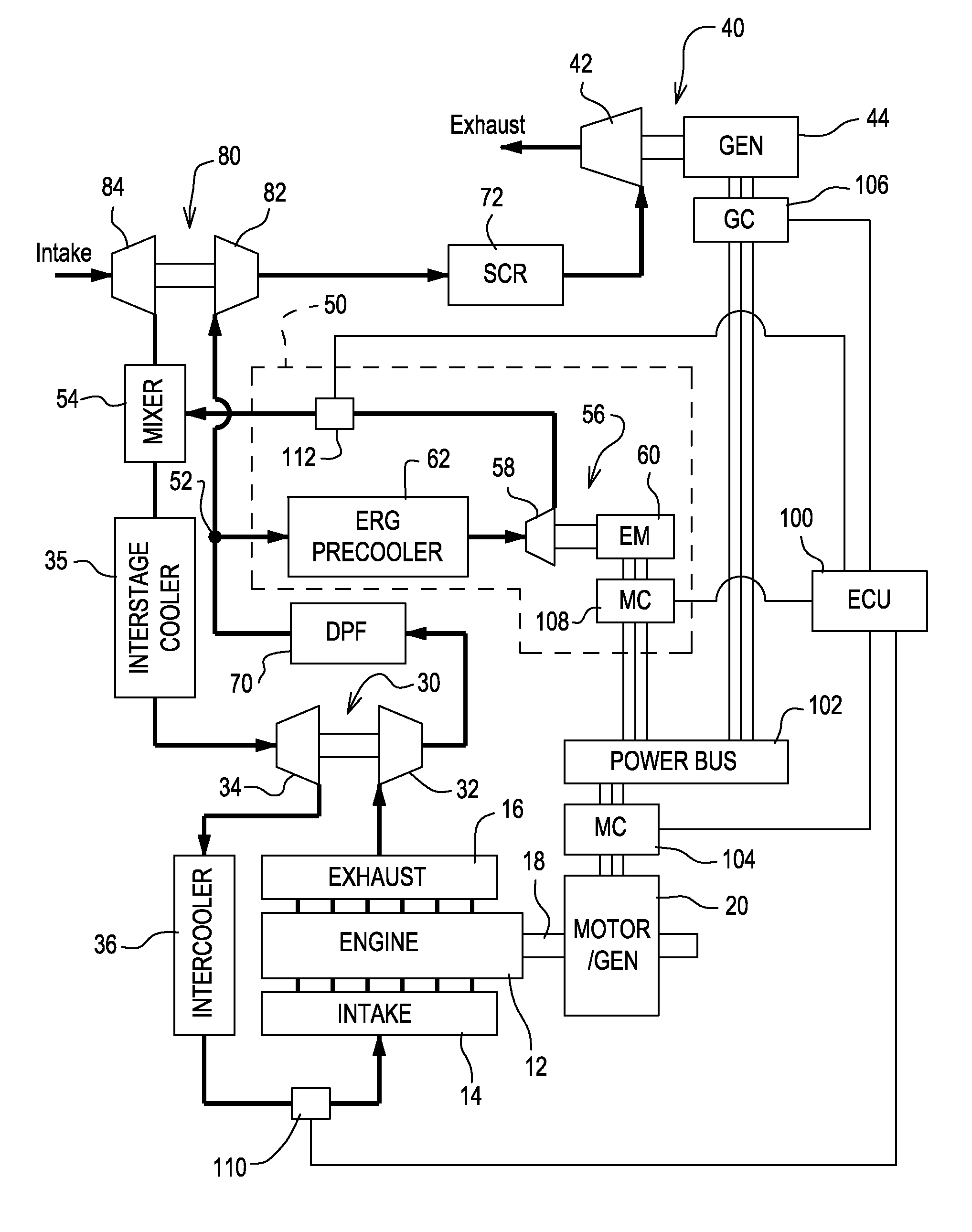
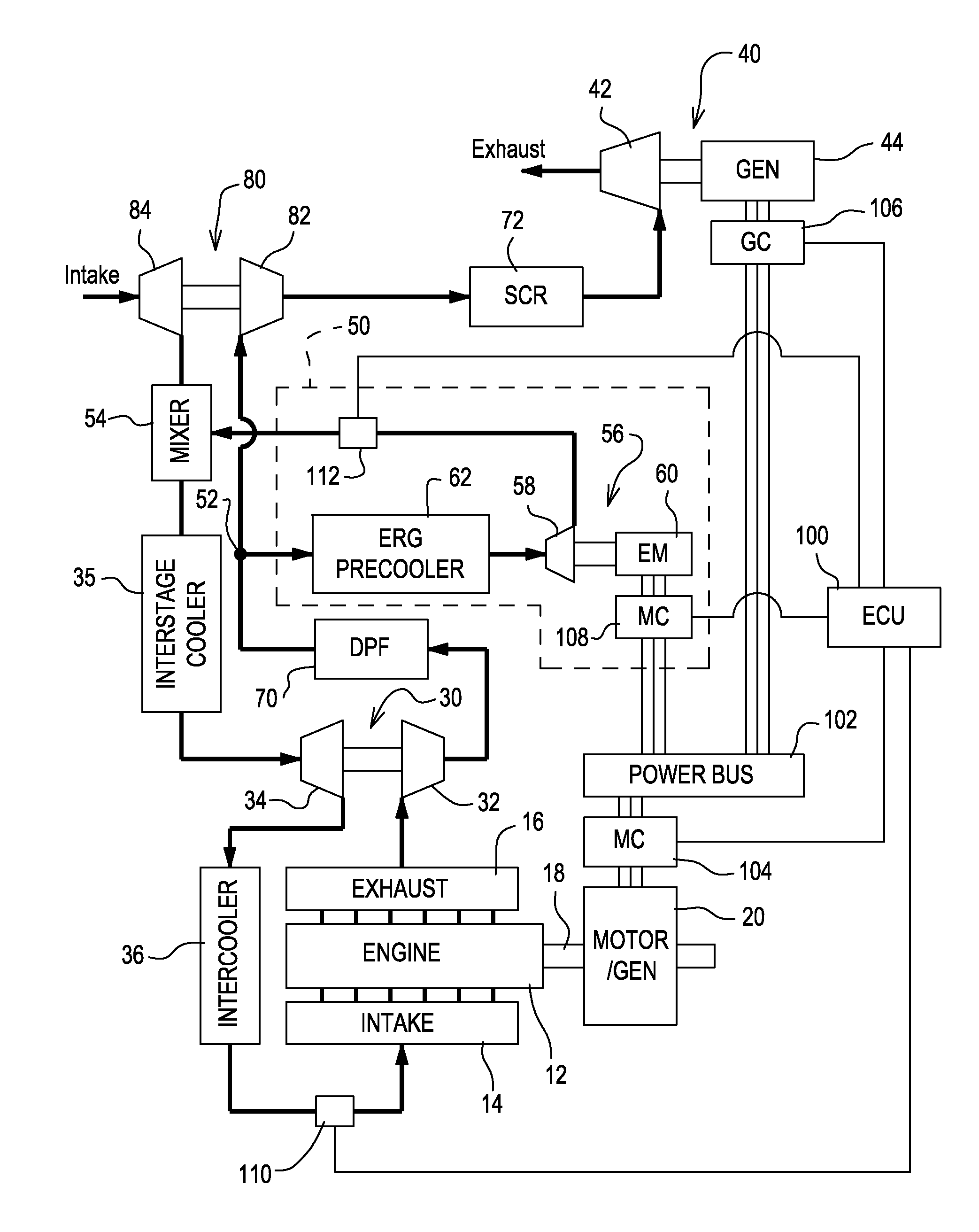
[0010]FIG. 1 shows a schematic for an IC engine 10 that will be well understood by one of ordinary skill in the art. In the schematic the engine 10 is shown with an engine block 12 for internal combustion, an intake manifold 14 for supplying air to the engine block 12 for combustion, an exhaust manifold 16 for collecting exhaust gas from the engine block 12 after combustion, and an output shaft 18 for transferring energy from internal combustion to power external loads. The engine block 12 is representative of any type of internal combustion engine, but is preferably for a reciprocating-type engine having one or more combustion chambers. The engine 10 is further provided with an ECU 100 to monitor sensors and command various functions of the engine 10. Inherent in the ECU 100 is functionality to monitor or calculate engine 10 speed and load, and to command engine 10 functions such as increased or decreased combustion timing in response thereto. Although the system illustrated is app...


PUM


Abstract

An internal combustion engine defined as having an engine block for internal combustion, a high-pressure turbocharger for delivering pressurized intake air to the engine block, a low-pressure turbocharger for delivering pressurized intake air to the high-pressure turbocharger, a turbogenerator for recovering heat energy from the exhaust gas downstream of the low-pressure turbocharger to generate electricity, and an exhaust gas recirculation (EGR) system comprising an EGR-pump drawing exhaust gas from an EGR inlet located between the low-pressure and high-pressure turbocharger turbines, wherein the EGR-pump controllably delivers exhaust gas to an EGR mixer in the pressurized intake air stream at a location between the low-pressure and high-pressure turbocharger compressors. An electronic control unit (ECU) is adapted to command the EGR-pump to deliver a desired EGR flow-rate to the engine block based on look-up tables and either open-loop and/or closed-loop control algorithms.

Description

FIELD OF THE INVENTION[0001]The present invention relates to internal combustion engines, and more particularly, to engines with turbogenerator systems.BACKGROUND OF THE INVENTION[0002]Internal combustion (IC) engines are widely used to provide mechanical power in mobile and stationary applications. It is common for engines to use turbochargers to harness residual energy from the engine exhaust gases with a turbine driving a compressor to boost airflow to the engine. It is also known to use a power-turbine to harness additional mechanical power, or to drive an electrical generator. The later configuration is known as a turbogenerator.[0003]Exhaust emissions from IC engines are increasing regulated by law. In particular, most developed countries regulate emission levels of both Oxides of Nitrogen (NOx) and particulates of unburned hydrocarbons. To control NOx emissions, it is common to recirculate a portion of exhaust gas (EGR) with intake air for combustion in order to reduce combus...

Claims


Application Information

Patent Timeline
IPC IPC(8): F02B47/08F02B33/44H02K7/18
CPCF01N5/04F02B37/004F02B33/40F02B37/013F02B39/10F02B41/10F02B47/08F02D29/06F02M25/0711F02M25/0718F02M25/0727F02M25/0739F02M25/0754Y02T10/121Y02T10/144Y02T10/16Y02T10/163F02B29/0412F02M26/08F02M26/15F02M26/23F02M26/34F02M26/47Y02T10/12
Inventor VUK, CARL T.WINSOR, RICHARD W.
Owner DEERE & CO
Why Eureka
Try Eureka