Electrical connector with dual-function housing protrusions

a technology of dual-function housings and connectors, applied in the direction of coupling contact members, coupling device connections, printed circuits, etc., can solve the problems of reducing adversely affecting the reliability of signal transmission between the terminals, and the middle portion of the lga chip is liable to be deformed downwardly, so as to reduce the risk of accidental damage to an associated electronic package

Active Publication Date: 2008-05-13
HON HAI PRECISION IND CO LTD
View PDF13 Cites 5 Cited by
  • Summary
  • Abstract
  • Description
  • Claims
  • Application Information

AI Technical Summary

Benefits of technology

[0010]An object of the present invention is to provide an electrical connector for electrically connecting an electronic package such as an LGA chip with a circuit substrate such as a PCB, whereby the electrical connector is configured to minimize the risk of accidental damage to an associated electronic package.
[0011]Another object of the present invention is to provide an electrical connector configured so that terminals of the connector can accurately engage with the associated electronic package.
[0013]When terminals are installed near the projections, a common carrier strip connecting the terminals is bent down so that connecting sections of the carrier strip are received in corresponding recesses. Junction portions between the terminals and their respective connecting sections are cut, and a main body of the carrier strip having the connecting sections is removed. The recesses enable the carrier strip to be manipulated so that sufficient space is made available for cutting off of the connecting sections without interfering with the sidewall thereat. The projections provide precise fitting positioning of the LGA chip in the space. In addition, when a force is exerted down on the LGA chip to make the LGA chip engege with the terminals, the force is borne by and distributed among the raised portions and the protrusions of the walls. This protects the LGA chip from distortion or damage should the force be unduly great. This helps ensure that engagement between the connector and the LGA chip is accurate and reliable. Furthermore, when the force is exerted on the LGA chip to make pads of the LGA chip engage with the terminals, the protrusions can prevent the terminals from being laterally displaced so that the terminals accurately connect with the pads of the LGA chip. This ensures that engagement between the connector and the LGA chip is reliable.

Problems solved by technology

If the LGA chip is not securely retained, this can reduce the reliability of signal transmission between the terminals 61 and the LGA chip.
A middle portion of the LGA chip is liable to be deformed downwardly.
This can adversely affect the reliability of signal transmission between the terminals 61 and the LGA chip, and may even permanently damage the LGA chip.
When this happens, the contacting portions may not be accurately engaged with the corresponding pads, resulting in faulty electronic connection between the terminals 61 and the pads.

Method used


Image

  • Electrical connector with dual-function housing protrusions
  • Electrical connector with dual-function housing protrusions
  • Electrical connector with dual-function housing protrusions

Examples


Embodiment Construction

[0023]Reference will now be made to the drawings to describe the present invention in detail.

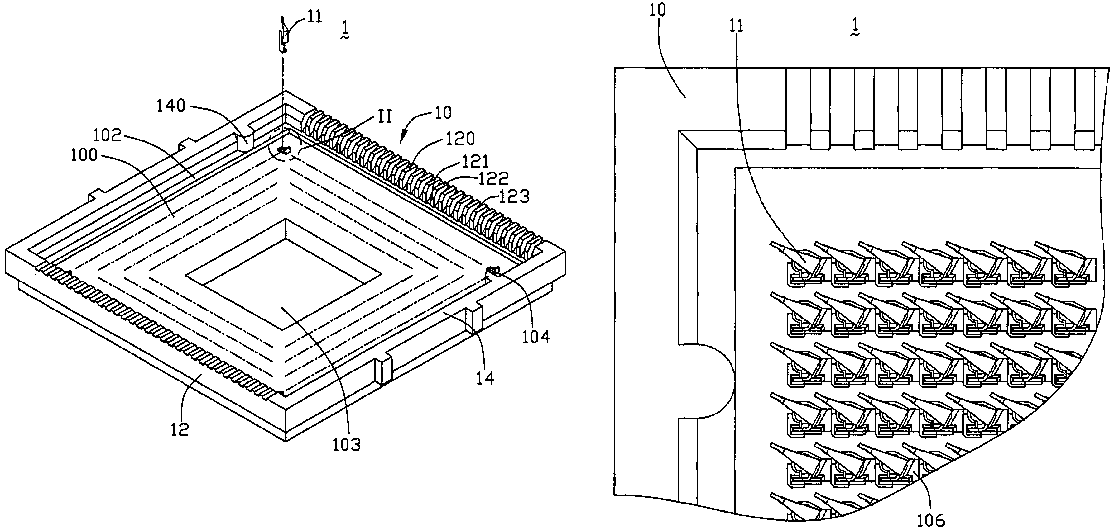
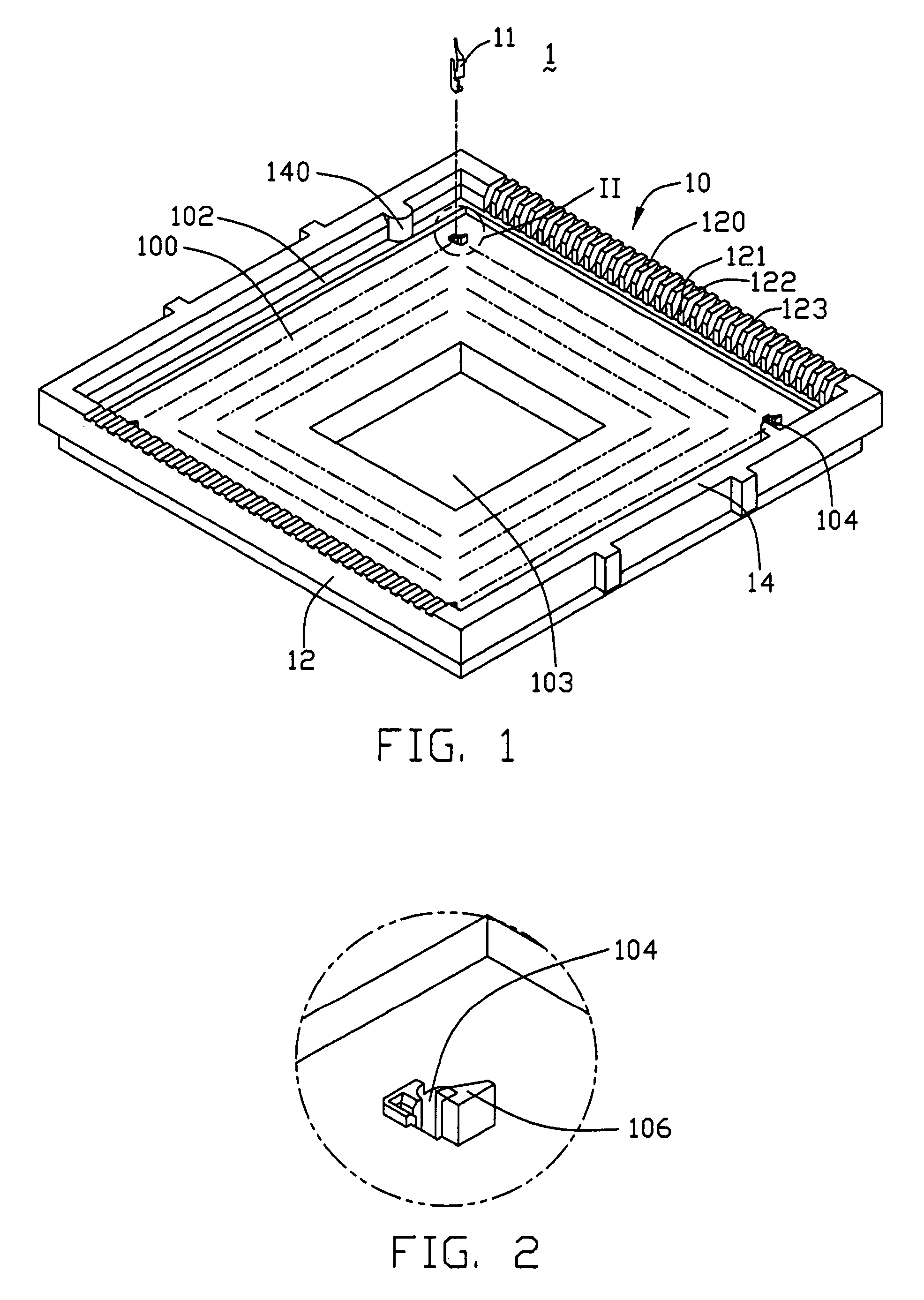
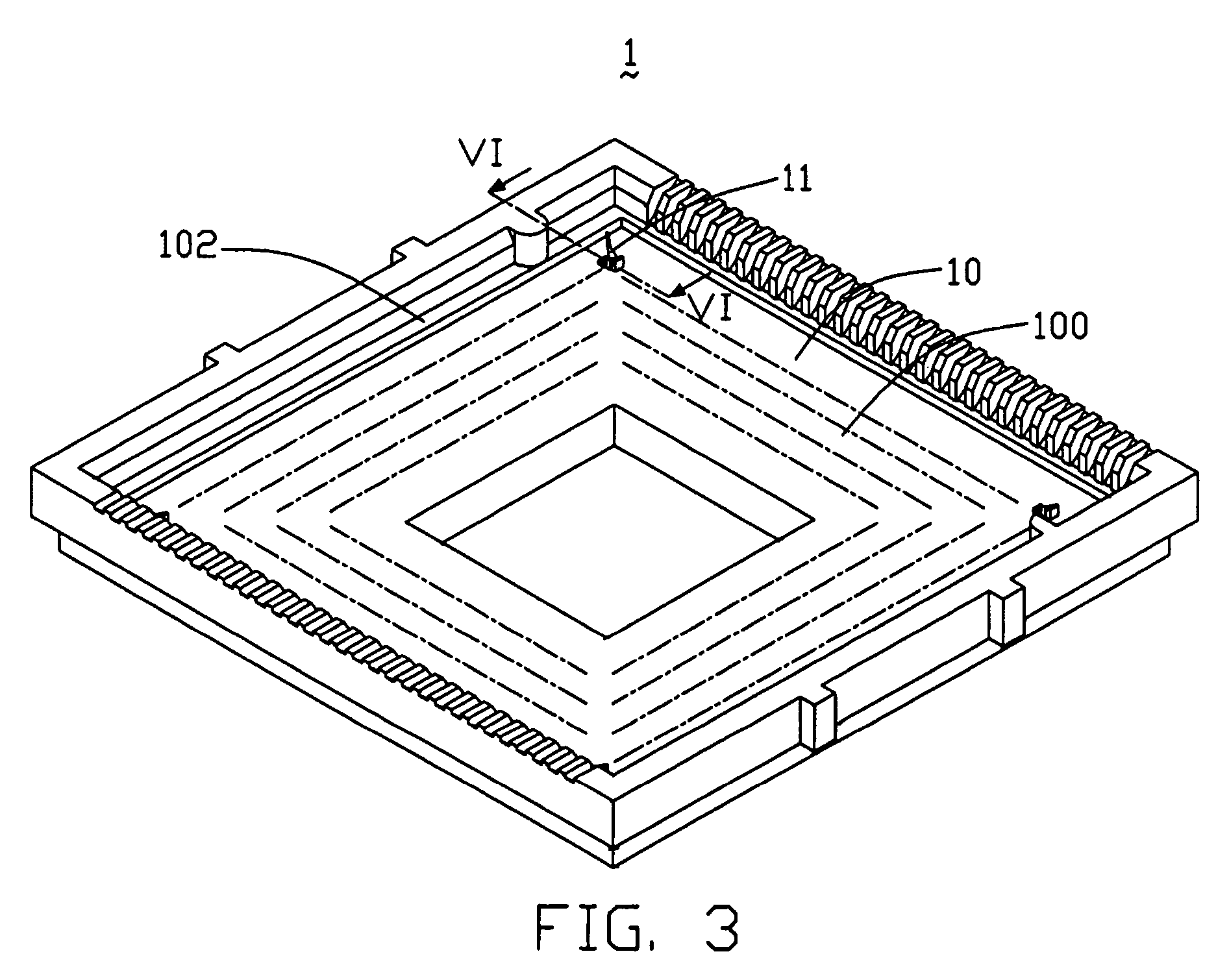
[0024]Referring to FIGS. 1 and 2, an LGA electrical connector 1 in accordance with the preferred embodiment of the present invention is used for electrically connecting an electronic package such as a land grid array (LGA) central processing unit (CPU) 2 with a circuit substrate such as a printed circuit board (PCB) (not shown). The LGA CPU 2 is hereinafter referred to as the LGA chip 2. The connector 1 comprises an insulative housing 10, and a multiplicity of conductive terminals 11 received in the housing 10. A carrier strip (not shown) comprises a row of the terminals 11, and a row of connecting sections respectively connecting the terminals 11 with a main body of the carrier strip. Referring also to FIGS. 6 and 7, each terminal 11 comprises a retaining portion 113 received in the housing 10, and a spring arm 114 extending slantingly upwardly from a top end of the retaining portion 113. A...


PUM


Abstract

An electrical connector (1) for connecting a land grid array (LGA) chip with a printed circuit board (PCB) includes a housing (10), and terminals (11) received in passageways (104) of the housing. The housing defines a base (100) and sidewalls (12, 14), the base and the sidewalls cooperatively defining a space therebetween for receiving the LGA chip. The base has a multiplicity of walls respectively between every two adjacent passageways along a length thereof, and four peripheral raised portions (102) extending upwardly and adjoining the sidewalls respectively. A multiplicity of protrusions (106) extends upwardly from the walls respectively. A height of the raised portions is the same as that of the protrusions. When a force is exerted down on the LGA chip to make the LGA chip engege with the terminals, a proportion of the force is borne by the protrusions and the raised portions.

Description

CROSS REFERENCE TO RELATED APPLICATION[0001]This application is a continuation-in-Part application with regard to the copending application Ser. No. 10 / 822,099 filed Apr. 9, 2004 having the same applicants and the same assignee with the instant application, and also relates to a co-pending U.S. patent application Ser. No. 10 / 318,593 filed on Dec. 13, 2002, entitled “ELECTRICAL CONNECTOR WITH DUAL-FUNCTION SIDEWALLS,” invented by Han-Yuan Ma, and assigned to the same assignee as the present invention.BACKGROUND OF THE INVENTION[0002]1. Field of the Invention[0003]The present invention relates to an electrical connector for electrically connecting an electronic package such as a land grid array (LGA) chip with a circuit substrate such as a printed circuit board (PCB), and particularly to a connector having protrusions that minimize the risk of accidental damage to an associated electronic package.[0004]2. Description of the Prior Art[0005]Land grid array (LGA) electrical connectors ar...

Claims


Application Information

Patent Timeline
Patent Type & Authority Patents(United States)
IPC IPC(8): H01R12/00H01R12/16H01R13/24
CPCH01R13/2442H01R12/7076
Inventor LIAO, FANG-JWUSZU, MING-LUN
Owner HON HAI PRECISION IND CO LTD
Why Eureka
Try Eureka