
Power strip modules and systems

a power strip and module technology, applied in the direction of coupling device details, electrical discharge lamps, coupling device connections, etc., can solve the problems of bulky plugs, difficult to insert or remove one or more plugs, and known power strips often have a bulky, static housing with a fixed number of outlets

Inactive Publication Date: 2008-05-13
IVANOVA IRINA +1
View PDF43 Cites 45 Cited by
  • Summary
  • Abstract
  • Description
  • Claims
  • Application Information

AI Technical Summary

Benefits of technology

The modular design improves access to bulky plugs, reduces spatial bulk, and allows for customizable configurations, enhancing usability and transportability while preventing outlet interference, thus addressing the limitations of traditional power strips.

Problems solved by technology

Power strips are found in numerous settings, including household and work environments, where there are not enough built-in outlets to supply power to the desired electrical devices.
But this can lead to several problems.
And even if adjacent outlets are not blocked, their close proximity often makes it difficult to insert or remove one or more plugs.
Fueling this frustration is the increasing need for bulky plugs, such as AC / DC adapter plugs with transformers, resulting from the growing demand for electronic and computer devices.
A second limitation is that known power strips often have a bulky, static housing with a fixed number of outlets.
But this renders such systems cumbersome and inconvenient to transport, especially when a user requires only a subset of outlets.
More generally, the bulky shape contributes to an unsightly appearance and can result in a safety hazard if the system is placed near foot traffic etc.
Consequently, known power strips are usually placed in hidden, hard-to-reach locations, further impeding access and use.

Method used


Image

  • Power strip modules and systems
  • Power strip modules and systems
  • Power strip modules and systems

Examples


Embodiment Construction

[0033]The present invention addresses the limitations of known power distribution systems, in particular power strips. These limitations include impeded plug access and removal, overall bulkiness, and limited adaptability. To address these problems, the present application discloses power distribution systems based on one or more compact, versatile, and adaptable modules.

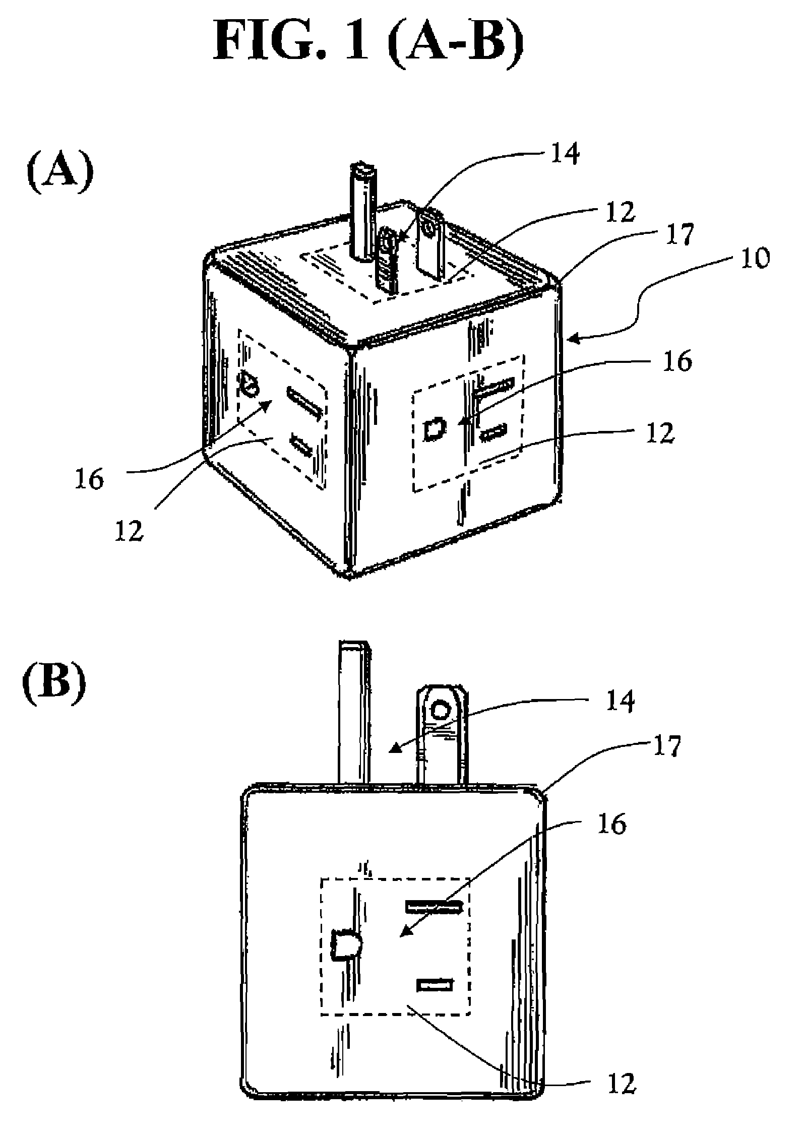
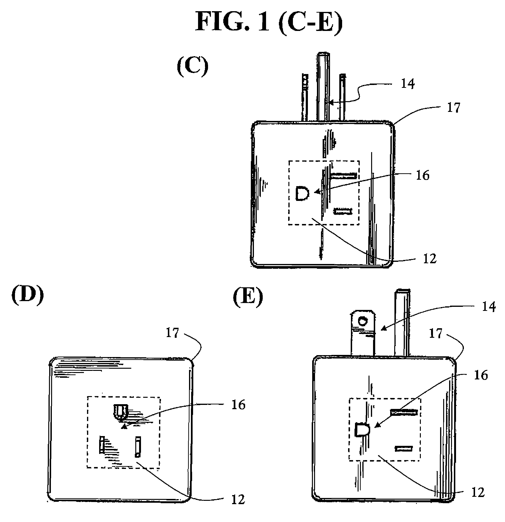
[0034]A module of the present invention includes a housing that can be formed of any rigid material, such as plastic, metal, ceramic, wood, and the like, and combinations thereof. The housing provides multiple faces that may be suitable for locating electrical connectors. Preferably, each housing face is suitable for locating an electrical connector. In one set of embodiments, the housing has the approximate shape of a rectangular block, providing six suitable faces. More particularly as exemplified by modules 10, 20, 22, 24, and 26 in FIGS. 1-3, the housing has the approximate shape of a cube having six suitable fa...


PUM


Abstract

A power distribution system, in particular a power strip, includes one or more modules. The module housing typically approximates the shape of a rectangular or triangular block. In a preferred embodiment, the module approximates a cube and provides six major surfaces, each approximately at right angle to its neighboring major surfaces. Preferably, one major surface provides a male plug, while each remaining major surface provides a single female electrical socket. Such a module is spatially compact, aesthetically and visually appealing, and relieves the excessive bulk of oversized plugs that would otherwise block access to one or more sockets. A single module offers a stand-alone socket adapter, while a plurality of compatible modules can be joined together to form an adjustable power strip. Modules can be distinguished, such as by color, to specify function or use, and compatible modules can be conveniently provided in a kit.

Description

CROSS-REFERENCE TO RELATED APPLICATIONS[0001]This application is a continuation in part of U.S. Design patent application Ser. No. 29 / 242,439 filed on Nov. 11, 2005, and this application claims priority to U.S. Provisional Patent Application Ser. No. 60 / 760,992 filed on Jan. 19, 2006. Each of the above-identified patent applications is incorporated herein, by reference, in its entirety.FIELD OF THE INVENTION[0002]This invention relates generally to electrical adapters and power distribution systems and, particularly to power strip modules and power strip systems.BACKGROUND OF THE INVENTION[0003]Power distribution systems, such as power strips, are commonly used to distribute a power input to multiple outlets, e.g., female connectors, sockets, jacks. A common example of such a system is a power strip, or variant thereof, which has one end that is fitted with an electrical plug, i.e., a male connector, and another end that is connected to a fixed housing that has multiple outlets.[000...

Claims


Application Information

Patent Timeline
Patent Type & Authority Patents(United States)
IPC IPC(8): H01R25/00
CPCH01R9/2408H01R13/514H01R25/003
Inventor IVANOVA, IRINASAGDULLAEV, BOTIR T.
Owner IVANOVA IRINA
Learn More