Virtual load balancing across a network link

a virtual load and network link technology, applied in data switching networks, frequency-division multiplexes, instruments, etc., can solve the problems of information moving across the remaining uncongested virtual channels, packet dropping associated with the particular congested virtual channel,

Active Publication Date: 2008-05-13
EXTREME NETWORKS INC
View PDF3 Cites 70 Cited by
  • Summary
  • Abstract
  • Description
  • Claims
  • Application Information

AI Technical Summary

Problems solved by technology

By directing the information across the same corresponding virtual channels in both the first and second network switches, any congestion in the second network switch results only in packet dropping associated with the particular congested virtual channel.
However, information continues to move across the remaining uncongested virtual channels.

Method used


Image

  • Virtual load balancing across a network link
  • Virtual load balancing across a network link
  • Virtual load balancing across a network link

Examples


Embodiment Construction

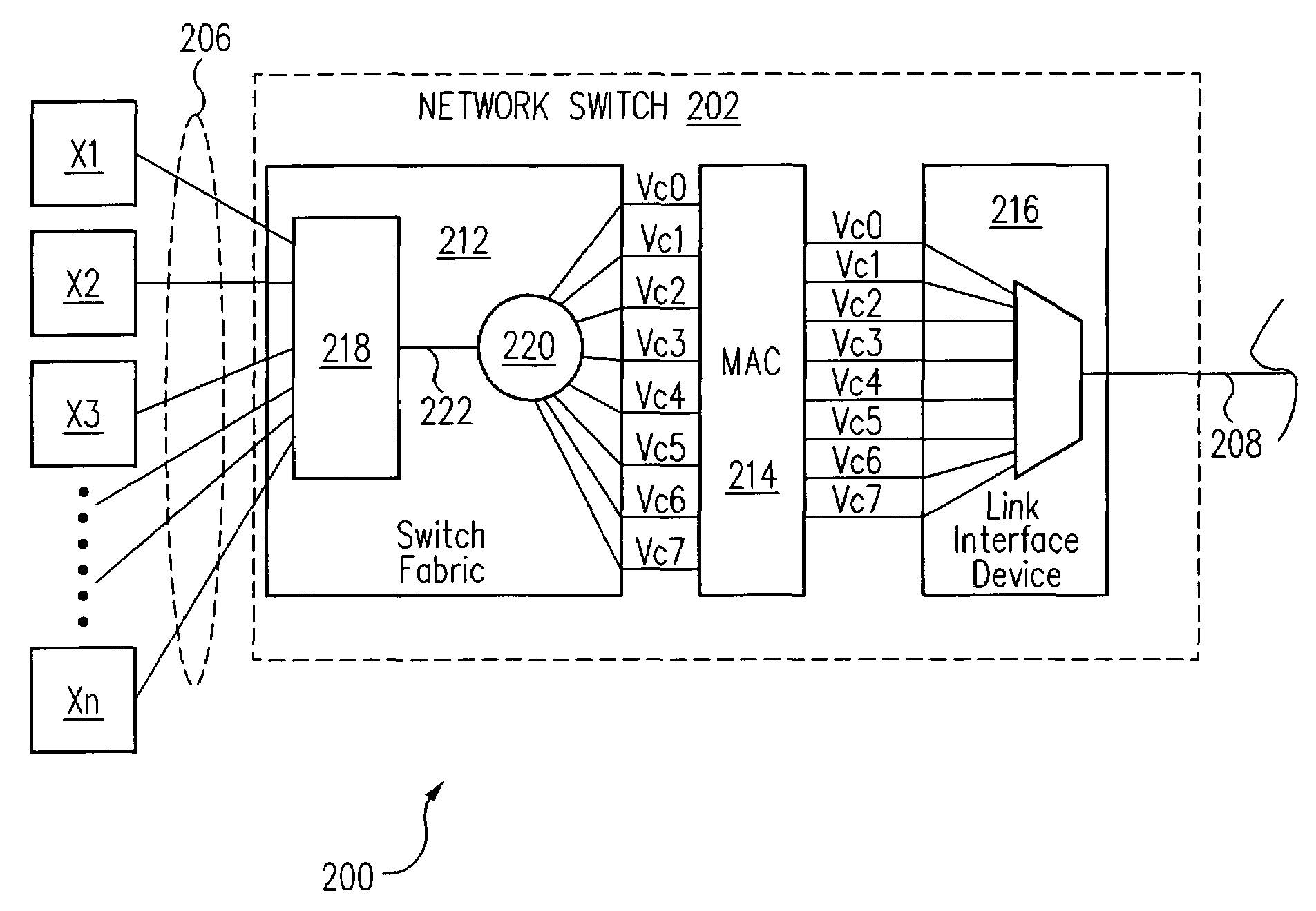
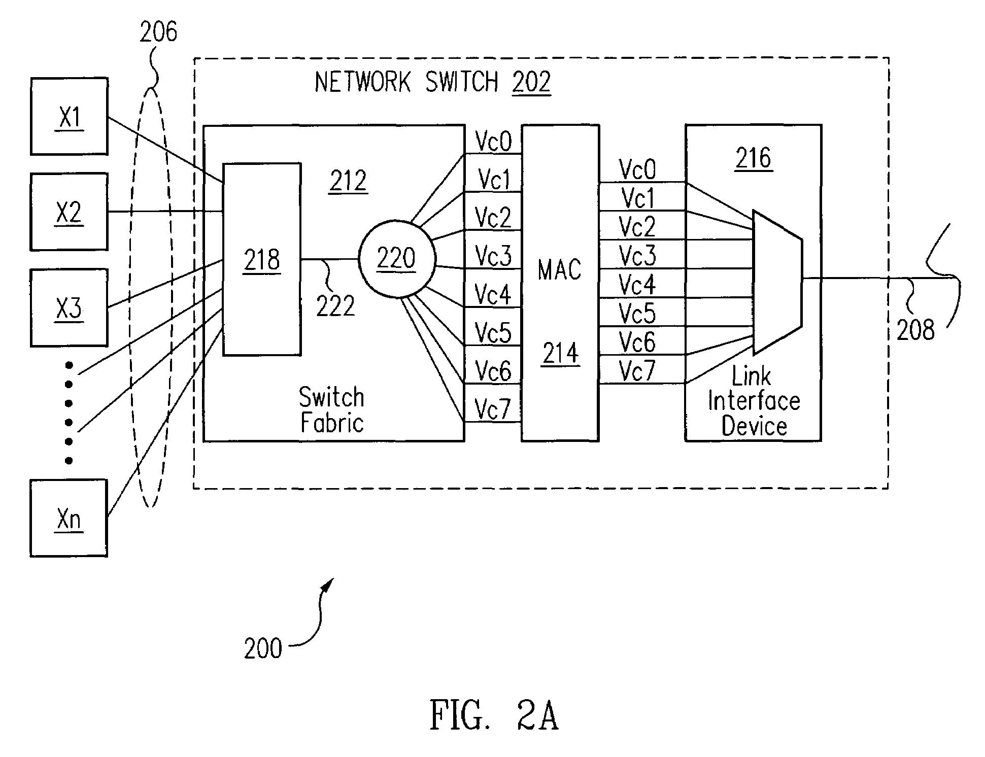
[0019]In accordance with one embodiment of the present invention, information is directed across the same corresponding virtual channels Vc0-Vc7 in both a transmit network switch 202 (FIGS. 2A and 2B) and a receive network switch 204. As a result, any congestion in receive network switch 204 results only in packet dropping associated with the particular congested virtual channel Vc0-Vc7. However, information continues to move across the remaining uncongested virtual channels Vc0-Vc7. As a result, even if congestion occurs in receive network switch 204, information continues to flow across the single network link 208 between network switches 202 and 204, i.e., the single network link 208 is not shut down.

[0020]More particularly, FIG. 2 is a key to FIGS. 2A and 2B, which are a schematic diagram of a network 200 utilizing network switches 202, 204 in accordance with one embodiment of the present invention. Referring now to FIGS. 2A and 2B together, a plurality of transmitting network d...


PUM


Abstract

Information is directed across the same corresponding virtual channels in both a first network switch and a second network switch. As a result, any congestion in the second network switch results only in packet dropping associated with the particular congested virtual channel. However, information continues to move across the remaining uncongested virtual channels. As a result, even if congestion occurs in the second network switch, information continues to flow across the single network link between the first and second network switches, i.e., the single network link is not shut down.

Description

BACKGROUND OF THE INVENTION[0001]1. Field of the Invention[0002]The present invention relates generally to load balancing in a network device.[0003]2. Description of the Related Art[0004]FIG. 1 is a schematic diagram of a network 100 in accordance with the prior art. Network 100 includes a plurality of transmitting network devices X1-Xn, which transmit information over network 100 using network switches 104, 106.[0005]Transmitting network devices X1-Xn are coupled by a plurality of network device links 108 to network switch 104. Illustratively, network device links 108 are 100 Mb / s links. Network switch 104 arbitrates and allocates bandwidth between network device links 108 and thus transmitting network devices X1-Xn.[0006]Network switch 104 is coupled to network switch 106 with a network link 110, e.g., a 1 Gb / s ethernet link. A plurality of receiving network devices R1-Rn are coupled by a plurality of network device links 114 to network switch 106. Illustratively, network device l...

Claims


Application Information

Patent Timeline
Patent Type & Authority Patents(United States)
IPC IPC(8): H04J1/16
CPCH04L47/10H04L47/125H04L47/32
Inventor CIMINO, DANIEL J.HADDOCK, STEPHEN R.KNUDSTRUP, MATTHEW T.
Owner EXTREME NETWORKS INC
Why Eureka
Try Eureka