Milling apparatus

a technology of milling apparatus and nozzle, which is applied in the direction of shaping cutters, manufacturing tools, transportation and packaging, etc., can solve the problems of increasing the space occupied by the milling apparatus, difficult to deal with pur and eva-based hot melt adhesive having a week's adhesion

Inactive Publication Date: 2008-05-20
HORIZON INTERNATIONAL INC
View PDF19 Cites 4 Cited by
  • Summary
  • Abstract
  • Description
  • Claims
  • Application Information

AI Technical Summary

Benefits of technology

[0014]Accordingly, an object of the present invention is to provide a milling apparatus incorporated in an adhesive book binding system, in which an EVA-based hot melt adhesive and a PUR-based hot melt adhesive can be selectively used without causing an increase in an occupied space.
[0018]According to the present invention, there is provided a compact adhesive book binding system in which the EVA-based hot melt adhesive and the PUR-based hot melt adhesive can be selectively used with one milling apparatus.

Problems solved by technology

However, the EVA-based hot melt adhesive has week adherence.
Since the PUR-based hot melt adhesive does not melt again once it has cured, it is not easy to deal with the PUR-based hot melt adhesive.
As a result, there is a problem that a space occupied by the milling apparatus is increased, and the adhesive book binding system becomes large in size.

Method used


Image

  • Milling apparatus
  • Milling apparatus
  • Milling apparatus

Examples


Embodiment Construction

[0026]A preferred embodiment of the present invention will be explained in detail with reference to the accompanying drawings.

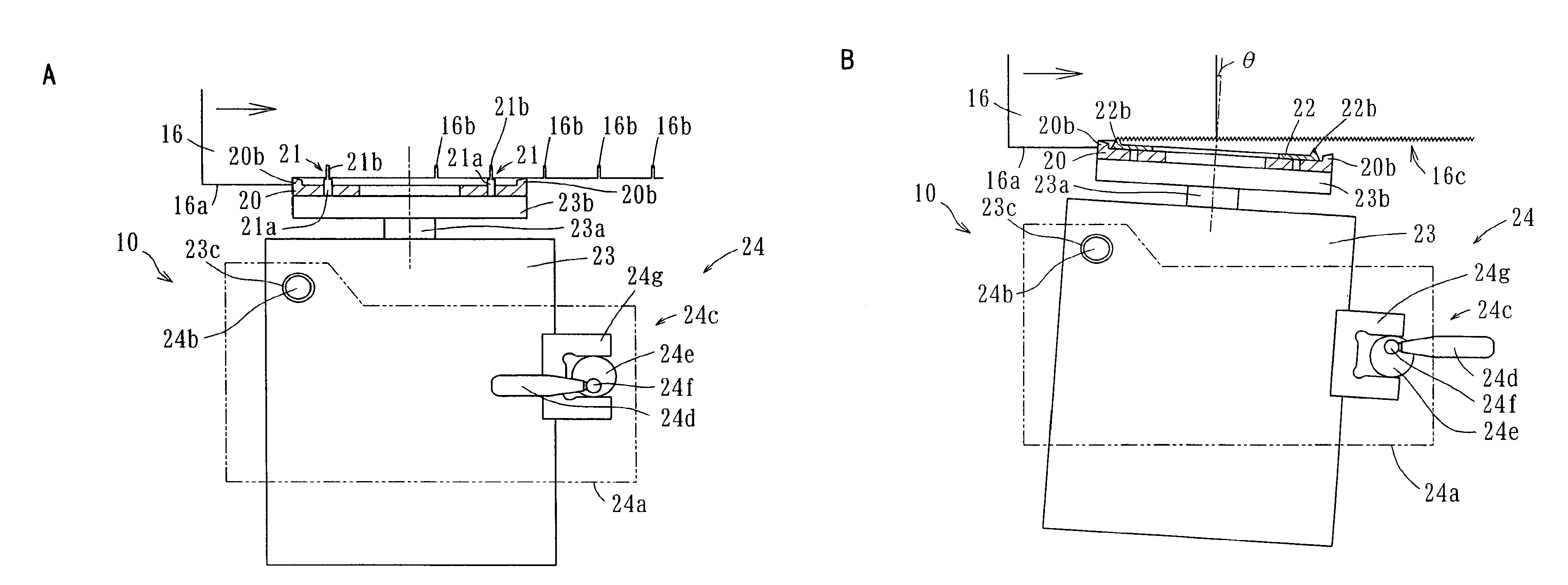
[0027]A milling apparatus 10 in accordance with the present invention is provided with a drive apparatus 23 having a rotational drive shaft 23a extending upwardly, a disc-shaped milling cutter 20 concentrically connected to a top end of the rotational drive shaft 23a and arranged in a plane perpendicular to the rotational drive shaft 23a, a shallow groove cutter 22 or a deep groove cutter 21 attached to an upper surface of the milling cutter 20, and a mechanism for tilting the drive apparatus 24, as shown in FIGS. 3A and 3B.

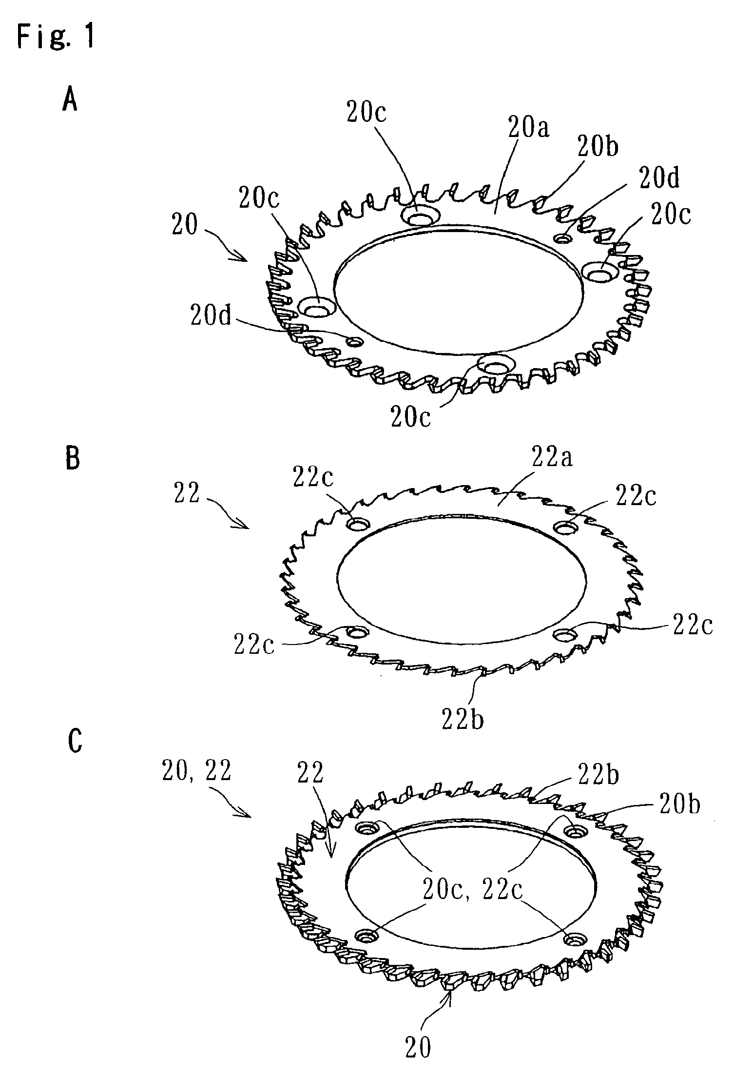
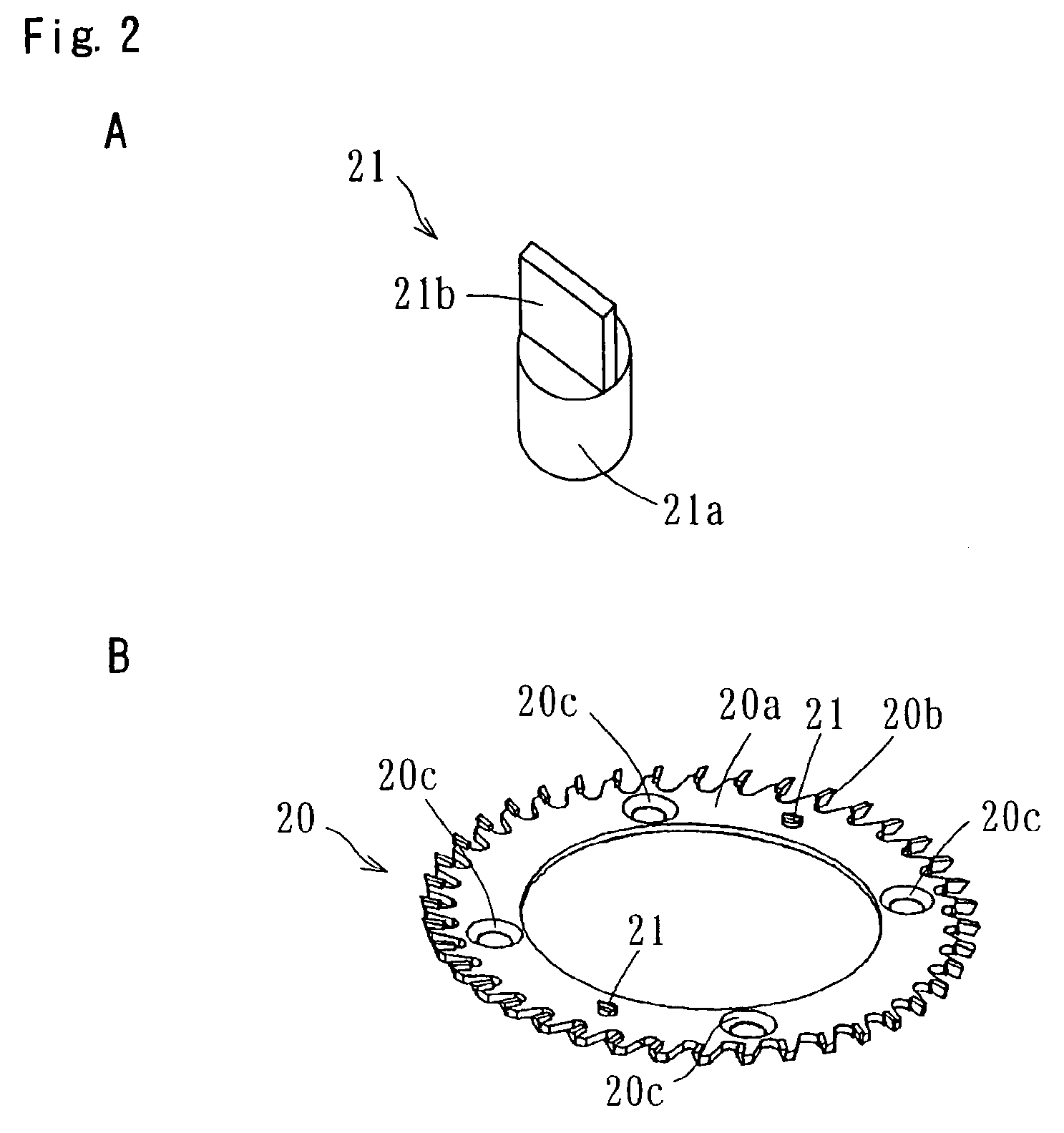
[0028]The milling cutter 20 has an annular and tabular blade base 20a, and a large number of trimming blades 20b upwardly protruding from an outer periphery of the blade base 20a, as shown in FIG. 1A. The milling cutter 20 has a mounting hole 20c for attaching the shallow groove cutter 22 and a hole 20d for attaching the deep groove cutter...


PUM

PropertyMeasurementUnit
circumferenceaaaaaaaaaa
angleaaaaaaaaaa
timeaaaaaaaaaa

Abstract

The milling apparatus (10) is arranged in such a manner that the deep groove cutter (21) is attached to the milling cutter (20) and the rotational drive shaft (23a) is approximately orthogonal to a spine (16a) of a sheet bundle (16) by the mechanism for tilting the drive apparatus (24) when an EVA-based hot melt adhesive is used. The milling apparatus (10) is arranged in such a manner that the shallow cutter (22) is attached to the milling cutter (20) and the rotational drive shaft (23a) is tilted with respect to a conveying direction of the sheet bundle (16) by the mechanism for tilting the drive apparatus (24) when a PUR-based holt melt adhesive is used.

Description

BACKGROUND OF THE INVENTION[0001]1. Field of the Invention[0002]The present invention relates to a milling apparatus incorporated in an adhesive book binding system executing a series of adhesive book binding process while conveying a sheet bundle.[0003]2. Description of the Related Art[0004]As shown in FIGS. 4 and 5, a conventional adhesive book binding system 1 includes a sheet bundle receiving section 2, a milling section 3, a bonding section 4, and a book cover attaching section 5. The adhesive book binding system 1 is configured to sequentially convey a sheet bundle 16 received at the sheet bundle receiving section 2 to each of the sections while clamping it by a clamper 6, thereby executing respective adhesive book binding processes.[0005]The sheet bundle receiving section 2 receives the sheet bundle 16 formed by stacking sheets 15 supplied from a printer or a copier, etc. according to page number. In the sheet bundle receiving section 2, the sheet bundle 16 is clamped between...

Claims


Application Information

Patent Timeline
Patent Type & Authority Patents(United States)
IPC IPC(8): B23P23/04B42C5/04
CPCB42C5/04Y10S83/934Y10T409/309408Y10T409/309576Y10T29/5102Y10T407/1952Y10T83/0311Y10T83/9447
Inventor OUCHIYAMA, KONAKANISHI, HIROHITOFUKUDA, SHIGENOBUKAMBARA, KANTA
Owner HORIZON INTERNATIONAL INC
Why Eureka
Try Eureka