
Damper assembly and washing machine using the same

a technology of adampers and a washing machine, applied in the field of washing machines, can solve problems such as the effect of beating and rubbing on the washing machine, and achieve the effect of reducing the number of scuffs

Inactive Publication Date: 2008-05-20
LG ELECTRONICS INC
View PDF19 Cites 8 Cited by
  • Summary
  • Abstract
  • Description
  • Claims
  • Application Information

AI Technical Summary

Benefits of technology

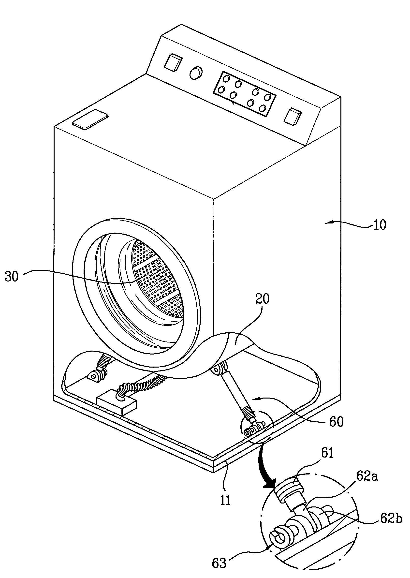
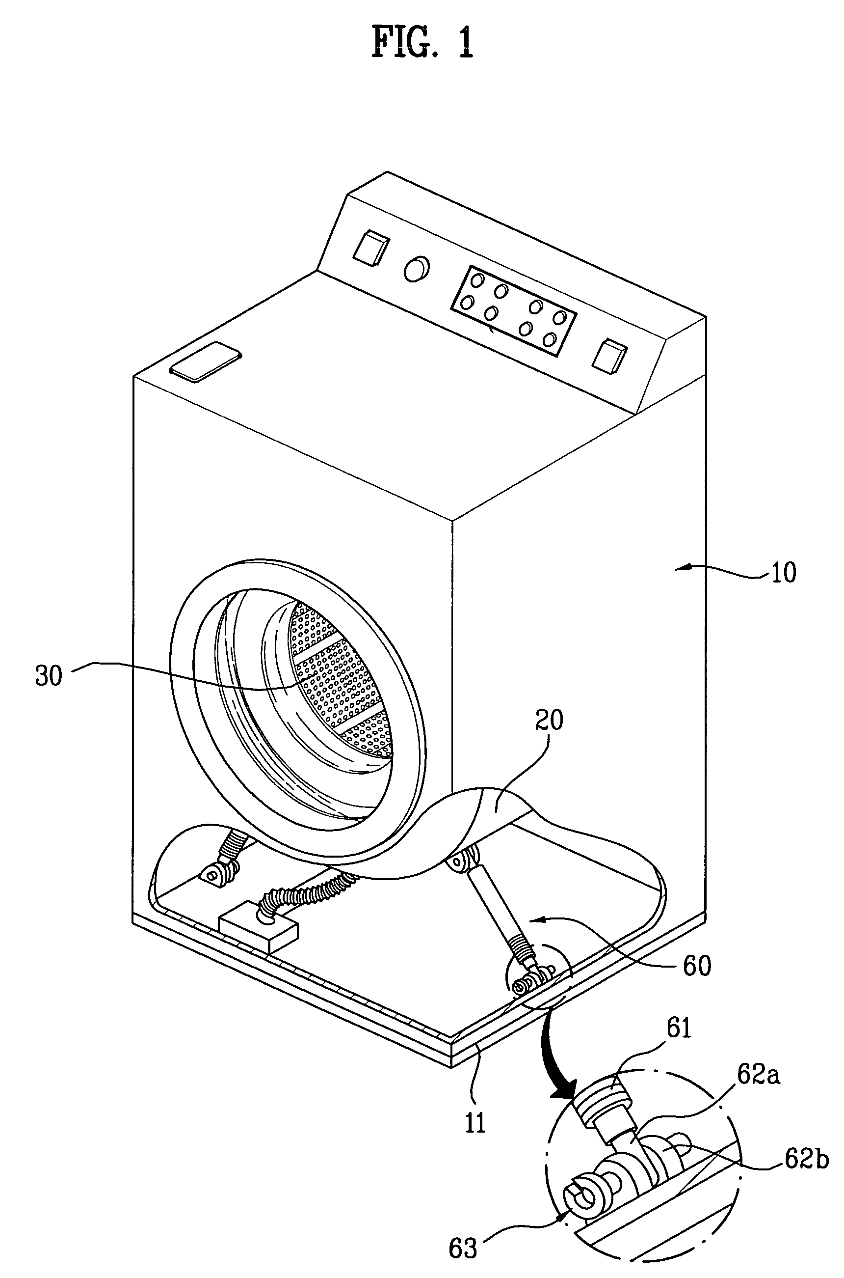
The present invention provides a damper assembly and a washing machine using the same that overcome the limitations and disadvantages of the related art. Specifically, the invention provides a damper pin that facilitates assembly and avoids being broken. The damper pin has a detent that is elastically transformed in a central axis direction of the damper pin when the damper pin penetrates through the connecting portions, and the detent restores to be locked on a lateral side of the connecting portions after thoroughly penetrating them. The detent has a front portion connected in one body to a lateral outside of the damper pin, a rear portion protruding outward from the damper pin, and a tilted surface between the front and rear portions. The detent has a cross-sectional area smaller than that of another portion of the detent, and a hole or hollow may be formed in the damper pin where the detent is connected to the lateral outside of the damper pin. The detent has a concave shape towards a center and a rim curved in a front-to-rear length. The damper assembly includes a damper attenuating a vibration transferred to the cabinet, and the cabinet has a first connecting portion and the damper has a second connecting portion at one end, and a damper pin penetrating the first and second connecting portions to secure them.

Problems solved by technology

Such a drum type washing machine avoids causing damage or ravel to the laundry, consumes less water, and brings about a washing effect of beating and rubbing.

Method used


Image

  • Damper assembly and washing machine using the same
  • Damper assembly and washing machine using the same
  • Damper assembly and washing machine using the same

Examples


first embodiment

[0035]Damper pins provided to the damper assembly according to various embodiments of the present invention are explained by referring to FIGS. 4A to 7 as follows. FIG. 4A is a layout of a damper pin provided to the damper assembly 600 according to the present invention, and FIG. 4B is a cross-sectional diagram of the damper pin taken along line A-A of FIG. 4A.

[0036]Referring to FIGS. 4A and 4B, a pin head 631 is formed at a rear part of the damper pin 630 to have an outside diameter greater than each inside diameter of the pin holes. Preferably, a front part of the damper pin 630 gradually decreases in diameter toward its front end to facilitate the damper pin 630 to be inserted in the pin holes of the damper connecting part 620. A hollow 632 is formed in the damper pin 630 and one side of the damper pin 630 is cut in a length direction of the damper pin 630. Hence, the damper pin 630 becomes elastic. Specifically, the damper pin 630 includes a detent 633. And, the detent 633 inclu...

second embodiment

[0040]In the present invention, a cross-sectional area of the front portion 643a of the detent 643 in a vertical direction to the length direction of the damper pin 640 is formed smaller than that of the rest portion of the detent 643 except the front portion 643a to enhance flexibility of the detent 643. For this, a hole 645 is formed in a portion where the detent 643 is connected to the lateral side of the damper pin 630. The hole 645, as shown in FIG. 5A, has a square shape. Yet, a shape of the hole 645 can be variously modified into circle, oval, and the like. And, a width of the hole 645 is about a quarter (¼) to a half (½) of the width of the front portion 643a of the detent 643. By the above configuration, the damper pin 640 enables to be smoothly passed through the pin holes of the damper connecting part 620 and the elasticity of the detent 643 is enhanced to prevent the breakage thereof.

[0041]FIG. 6A is a layout of a damper pin 650 provided to a damper assembly according to...


PUM


Abstract

A damper assembly and washing machine using the same, by which a damper pin configured to facilitate assembly is provided and by which a damper pin is configured to avoid breaking, are disclosed. The damper assembly includes a base having a first connecting portion, a damper having a second connecting portion at one end and attenuating a vibration transferred to the base, and a damper pin penetrating the first and second connecting portions to secure them, the damper pin having a slip-fit connection with the first and second connecting portions.

Description

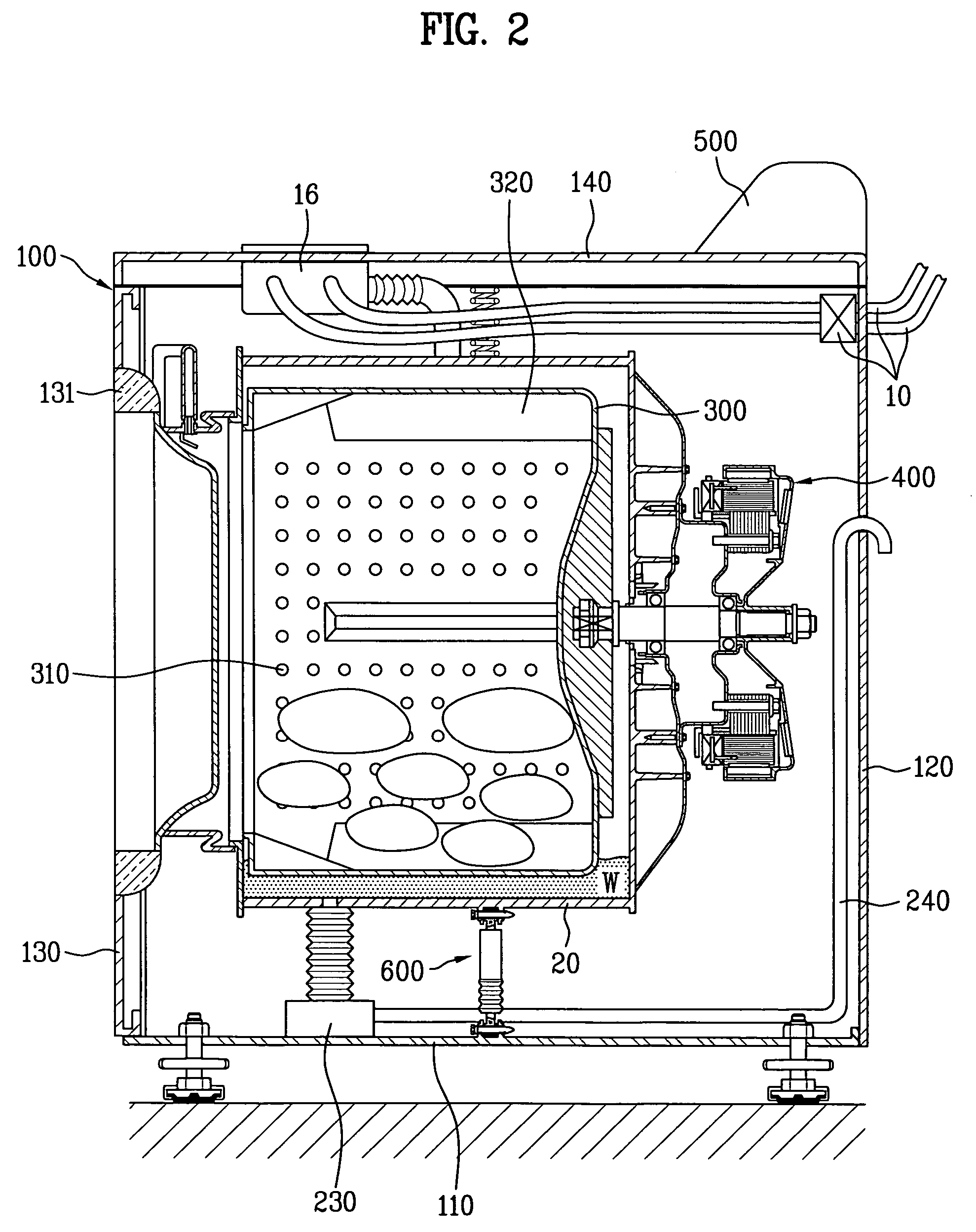
[0001]This application claims the benefit of Korean Application No. P2004-012603, filed on Feb. 25, 2004, which is hereby incorporated by reference.BACKGROUND OF THE INVENTION[0002]1. Field of the Invention[0003]The present invention relates to a washing machine, and more particularly, to a damper assembly and a washing machine using the same, in which a damper pin configured to facilitate assembly is provided.[0004]2. Discussion of the Related Art[0005]Generally, in a washing machine, a tub holds water and detergent inside and a laundry is put in a drum installed within the tub. And the drum is rotated to perform washing, rinsing, and dewatering. The washing machine is an apparatus for removing filth or dirt attached to the laundry using the detergent and mechanical energy applied thereto appropriately. Specifically, a drum, which is horizontally installed within a drum type washing machine, holds detergent, water, and laundry therein and is then rotated by a drive force of a motor...

Claims


Application Information

Patent Timeline
Patent Type & Authority Patents(United States)
IPC IPC(8): D06F37/22D06F37/20
CPCD06F37/20D06F37/22F16C11/02F16C2361/53F16C2340/00D06F39/125Y02B40/00
Inventor CHOI, KANG MO
Owner LG ELECTRONICS INC
Learn More