Vacuum tank assembly

a vacuum tank and assembly technology, applied in the field of toilets, can solve the problems of reducing the pumping efficiency of the vacuum pump, creating leaks in the joints,

Active Publication Date: 2008-05-20
DOMETIC APPLIANCES
View PDF27 Cites 4 Cited by
  • Summary
  • Abstract
  • Description
  • Claims
  • Application Information

AI Technical Summary

Problems solved by technology

Conventional dip tubes, as described in the above patents, are mechanically attached to the vacuum tank by a method known in the art such as screwing, gluing, etc. and may shift over time thus creating leaks in the joints and thus decreasing the pumping efficiency of the vacuum pump.

Method used


Image

  • Vacuum tank assembly
  • Vacuum tank assembly
  • Vacuum tank assembly

Examples


Embodiment Construction

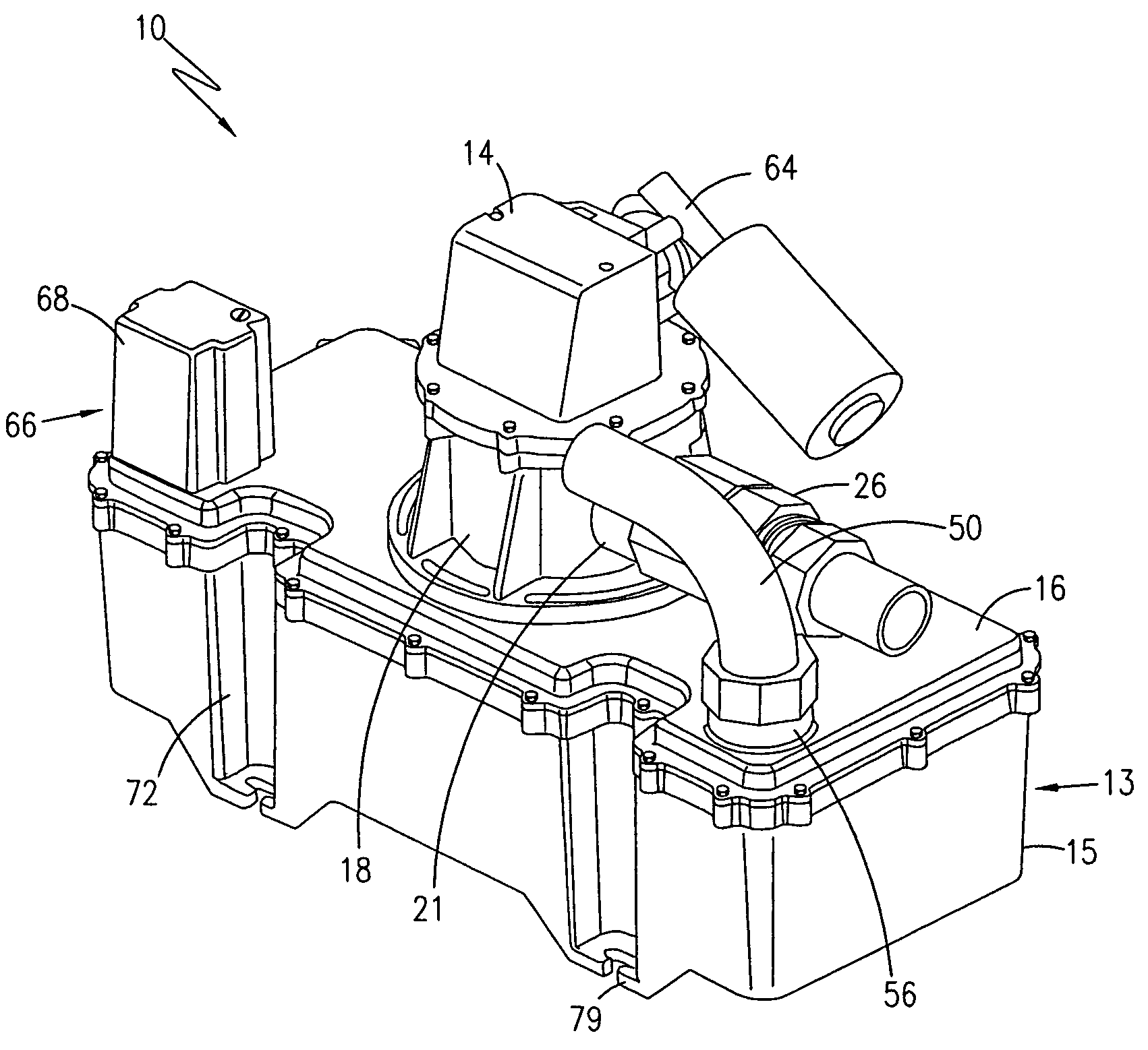
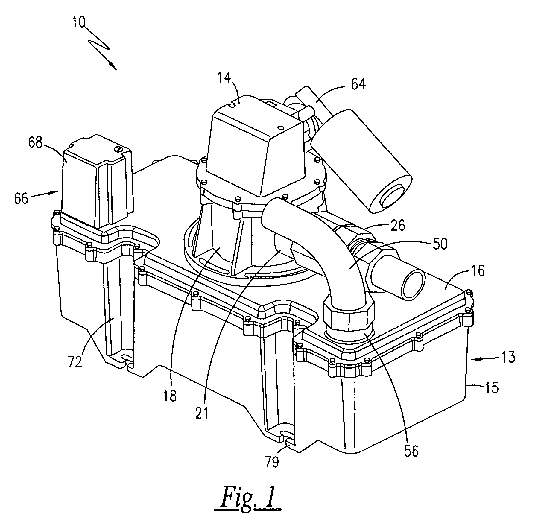
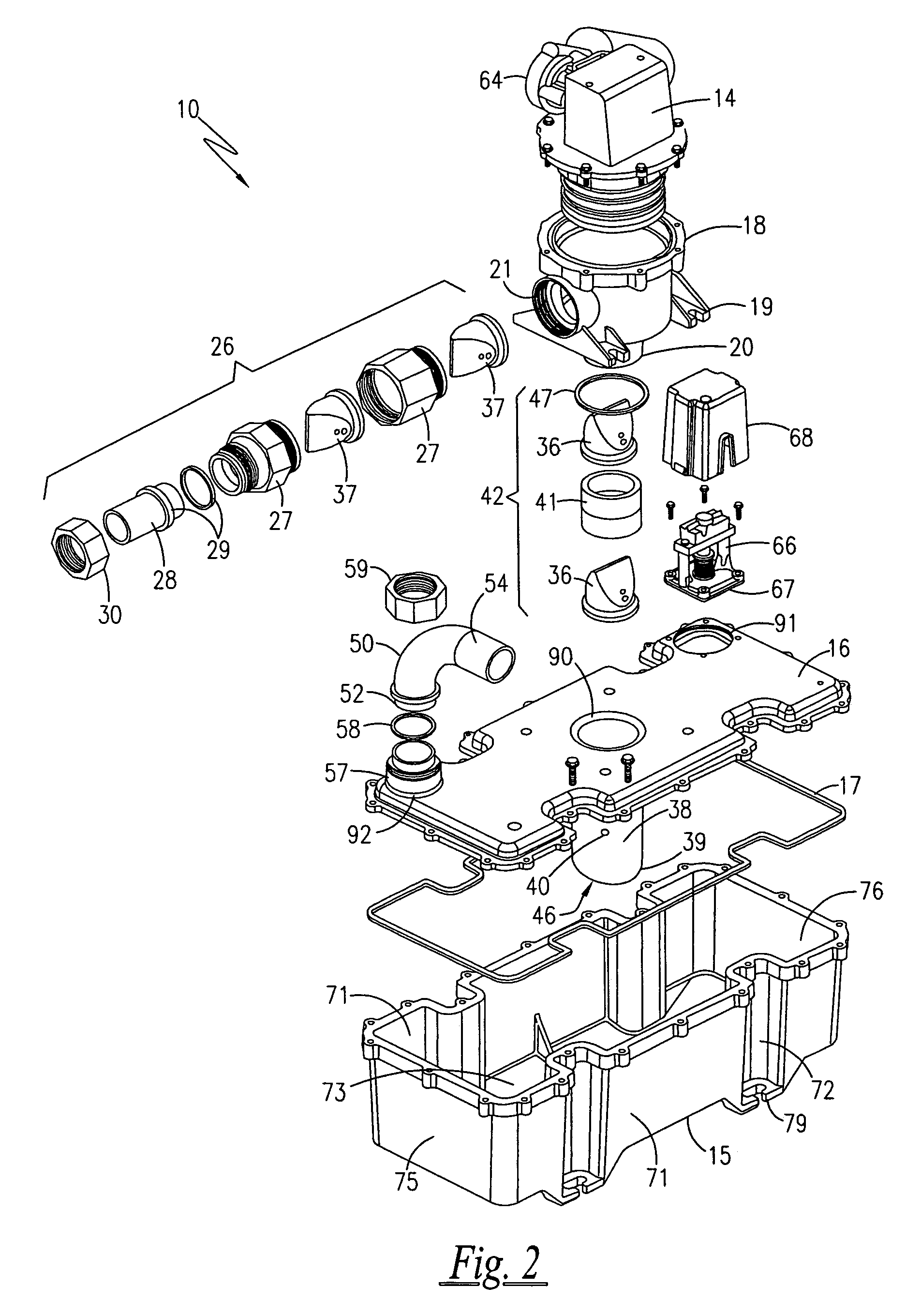
[0014]Referring now to the drawings, FIGS. 1 and 2 show an assembled and exploded view respectively of a vacuum tank assembly 10 in accordance with the present invention having a two-piece vacuum tank 13 construction. The vacuum tank 13 includes a hollowed-out body 15 and a removable top 16. The two-piece construction facilitates serviceability of the vacuum tank 13. The vacuum tank 13 may be constructed by any means known in the art such as injection molding, rotational molding, etc. and is preferably made of plastic, such as low density polyethylene. In the preferred embodiment, the vacuum tank 13 is injection molded to thereby provide tighter tolerances. The vacuum tank 13 preferably has a nominal wall thickness of about 0.188 inches (0.478 cm) with no flat surface area of greater than about 80 square inches (516.13 square cm). When assembled, the exterior of the vacuum tank 13 generally approximates a rectangular parallelepiped or prism configuration and may have a length of abo...


PUM

PropertyMeasurementUnit
diameteraaaaaaaaaa
diameteraaaaaaaaaa
thicknessaaaaaaaaaa

Abstract

A vacuum tank assembly is provided for use on an RV or a boat and includes a two-piece vacuum tank. The two-piece vacuum tank includes a body and a removable top with a gasket located between the body and removable top. A dip tube is integrated into the removable top, thus, forming an opening in the removable top and thereby reducing maintenance problems associated with mechanically attached dip tube assemblies. A vacuum pump is provided to pump the waste out of the vacuum tank into a holding tank.

Description

[0001]This application claims the benefit of U.S. Provisional Patent Application No. 60 / 621,194 filed on Oct. 22, 2004.FIELD OF THE INVENTION[0002]The present invention relates to toilets and more particularly, to a toilet and vacuum tank that is suitable for a boat, recreational vehicle, bus or the like.BACKGROUND OF THE INVENTION[0003]U.S. Pat. Nos. 5,621,924, 6,618,866, and 6,782,563, the disclosures all of which are herein incorporated by reference, disclose a vacuum tank construction for use with a vacuum toilet assembly that have a number of advantages over the prior art. While the vacuum tank of the present invention functions primarily in the same manner as the vacuum tanks disclosed in the above mentioned patents the construction of the present invention has several features that provide a number of advantages over these patents.[0004]For example, the construction according to the present invention is more compact both vertically and horizontally than the vacuum tanks discl...

Claims


Application Information

Patent Timeline
Patent Type & Authority Patents(United States)
IPC IPC(8): B67C3/16
CPCB60R15/04E03F11/00B63B29/16Y10T137/3109Y10T137/86035Y10T137/86348
Inventor SIGLER, JAMES A.EDMONDSON, LORNA K.MIKO, STEVEN L.
Owner DOMETIC APPLIANCES
Why Eureka
Try Eureka