Valve automated in-situ cleaning system for oil water separator

a technology of oil water separator and in-situ cleaning, which is applied in the direction of filtration separation, sedimentation settling tank, separation process, etc., can solve the problem of personnel being exposed to hazardous materials

a technology of oil water separator and in-situ cleaning, which is applied in the direction of filtration separation, sedimentation settling tank, separation process, etc., can solve the problem of personnel being exposed to hazardous materials

US7374668B1Inactive Publication Date: 2008-05-20THE UNITED STATES OF AMERICA AS REPRESENTED BY THE SECRETARY OF THE NAVY

Image

  • Valve automated in-situ cleaning system for oil water separator
  • Valve automated in-situ cleaning system for oil water separator
  • Valve automated in-situ cleaning system for oil water separator

Examples


Embodiment Construction

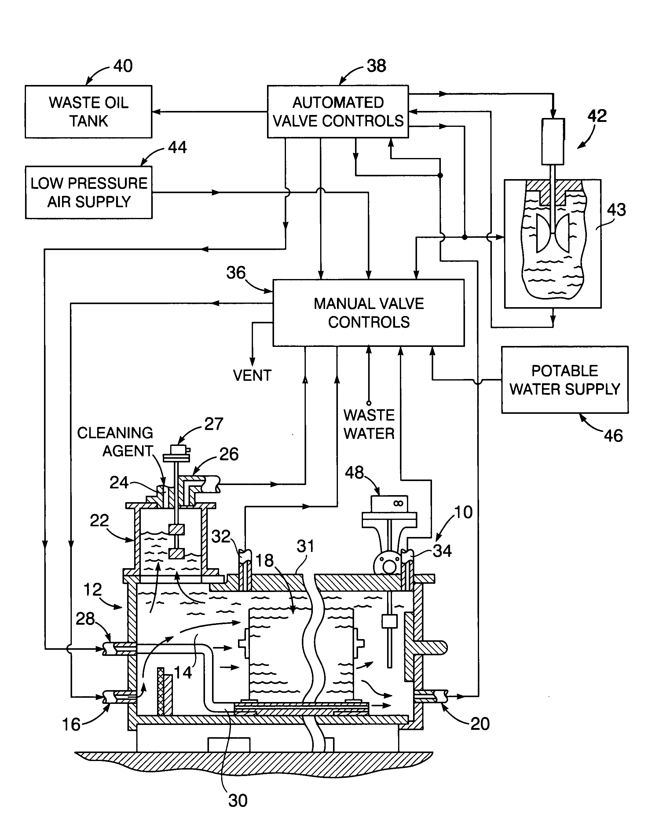
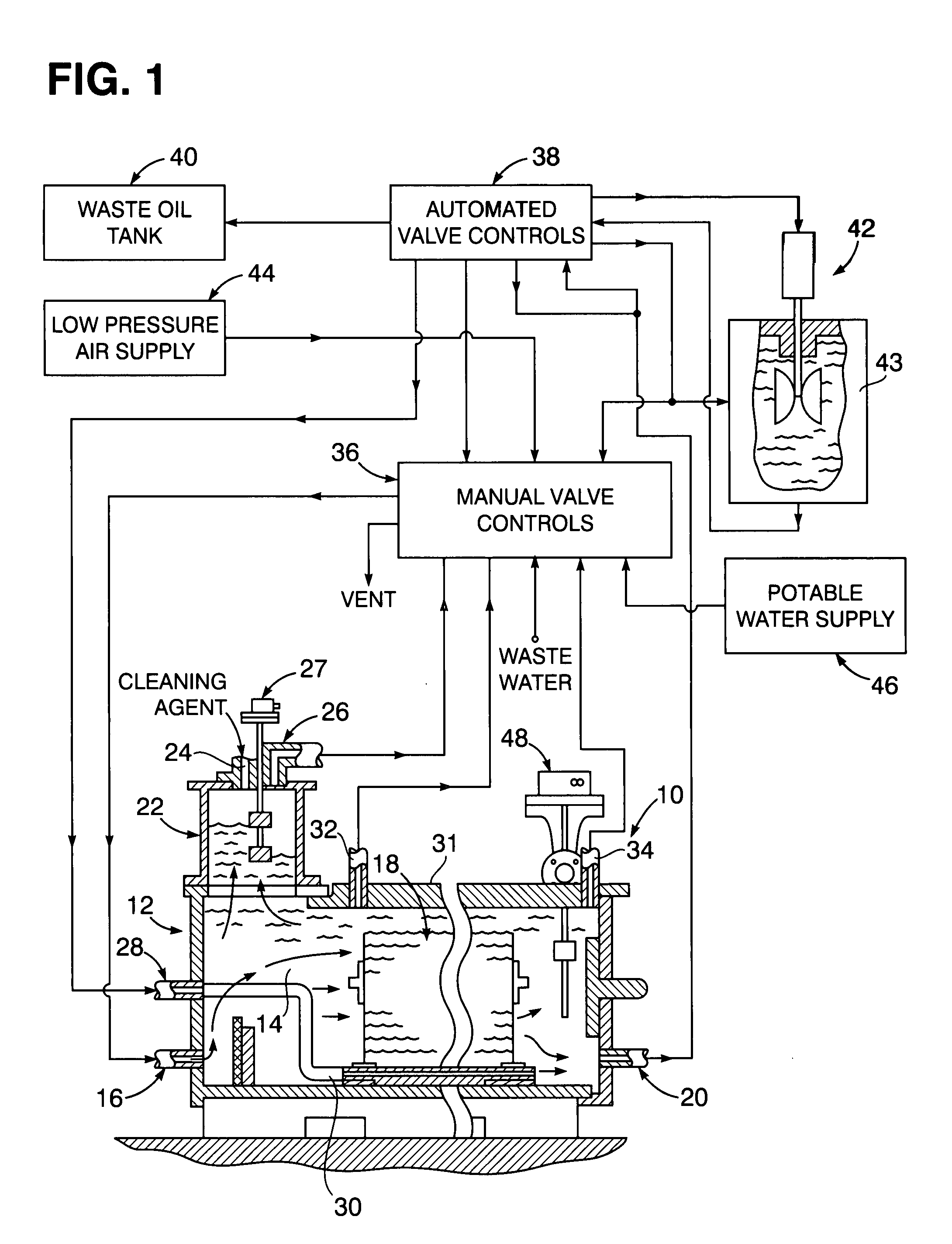
[0008]Referring now to the drawing in detail, FIG. 1 illustrates an oil / water separator 10, as disclosed in the aforementioned Lawson et al patent, with which the present invention is associated. The separator 10 has a tank 12 into which oily wastewater 14 enters through an intake fitting 16 at one end of the tank 12 adjacent the bottom thereof. The inflowing wastewater undergoes separation treatment by contact passage between plates of a stack 18, resulting in outflow of separated waste from the bottom of the tank 12 through a discharge fitting 20 extending from the end of the tank 12 opposite the end into which the intake fitting 16 extends. During such separation treatment within the tank 12, separated oil rises into an oil tower 22 mounted on top of the tank 12. A cleaning agent is injected into the oil tower 22 through an insert 24 on top thereof for periodic in-situ chemical cleaning of the plate stack 18 by removal of oil sludge deposited thereon as a result of the contact se...


PUM


Abstract

An oil/water separator tank having intake, discharge and vent fittings is conditioned for in-situ cleaning of the oil separator plate stacks positioned therein by selective opening of manual valves connected to each of such fittings. When so conditioned by opening of the manual valves, the in-situ cleaning is performed during repeated operational phases under automated control of solenoid operated and motor driven valves through which a plurality of sequential operational steps are performed, consisting of (a) low pressure air injected into an air sparging array within the separator tank, (b) supply of potable water into a mixing tank; (c) mixing of the potable water with the cleaning agent within the mixing tank; (d) introduction of the cleaning agent after the mixing thereof into the separator tank to enhance in-situ cleaning by dispersing the low pressure air from the air sparging array; and (e) drainage of collected waste oil from the separator tank into a waste oil tank.

Description


Claims


Application Information

Patent Timeline
20 May 2008
Publication
US7374668B1