Supercharge Your Innovation With Domain-Expert AI Agents!

Drill with releasably mounted cutting head

a cutting head and mounting plate technology, applied in the direction of cutting inserts, twist drills, manufacturing tools, etc., can solve the problem of less stable coupling

Active Publication Date: 2008-05-27
ISCAR LTD
View PDF24 Cites 32 Cited by
  • Summary
  • Abstract
  • Description
  • Claims
  • Application Information

AI Technical Summary

Benefits of technology

The design provides a stable and self-clamping mechanism for the cutting head on the tool shank, ensuring accurate alignment and improved stability during drilling operations, reducing the need for precise manufacturing tolerances and enhancing overall performance.

Problems solved by technology

If on the other hand, the cutting head and tool shank are designed to be coupled together with only one of the raised and lowered base surfaces in contact, then the coupling will be less stable.

Method used


Image

  • Drill with releasably mounted cutting head
  • Drill with releasably mounted cutting head
  • Drill with releasably mounted cutting head

Examples


Embodiment Construction

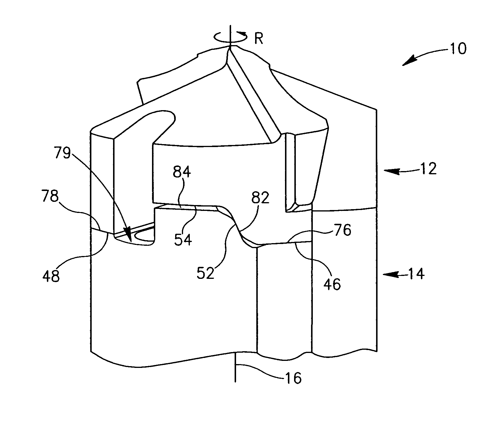
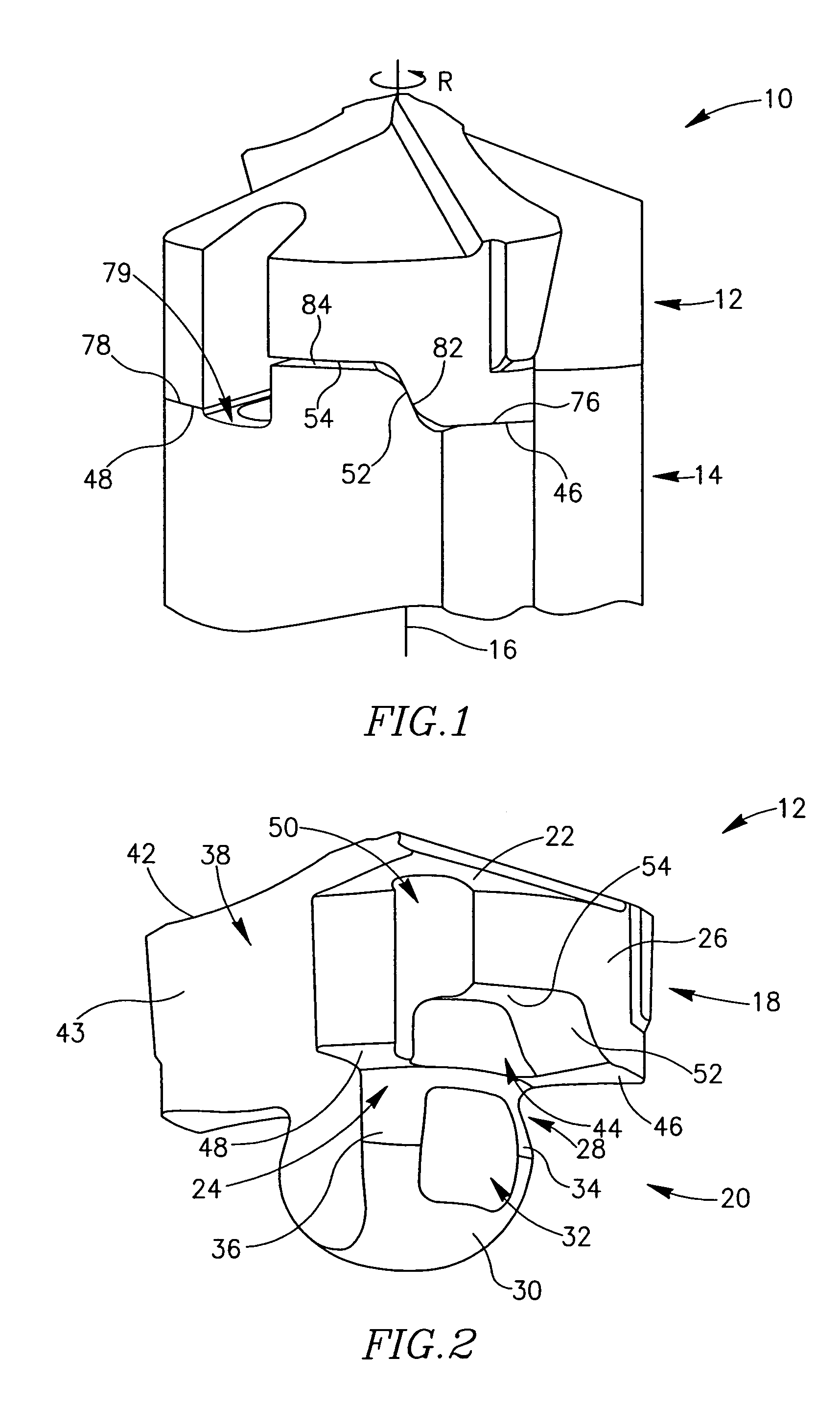
[0033]Attention is drawn to the figures showing a drill 10 (FIG. 1) for drilling holes in metal work pieces. The drill 10 comprises a cutting head 12 releasably mounted on a forward end of a tool shank 14, having a common longitudinal axis of rotation 16 defining a direction of rotation R. The cutting head 12 is typically made of hard wear resistant material such as cemented carbide, and the tool shank 14 is typically made of steel.

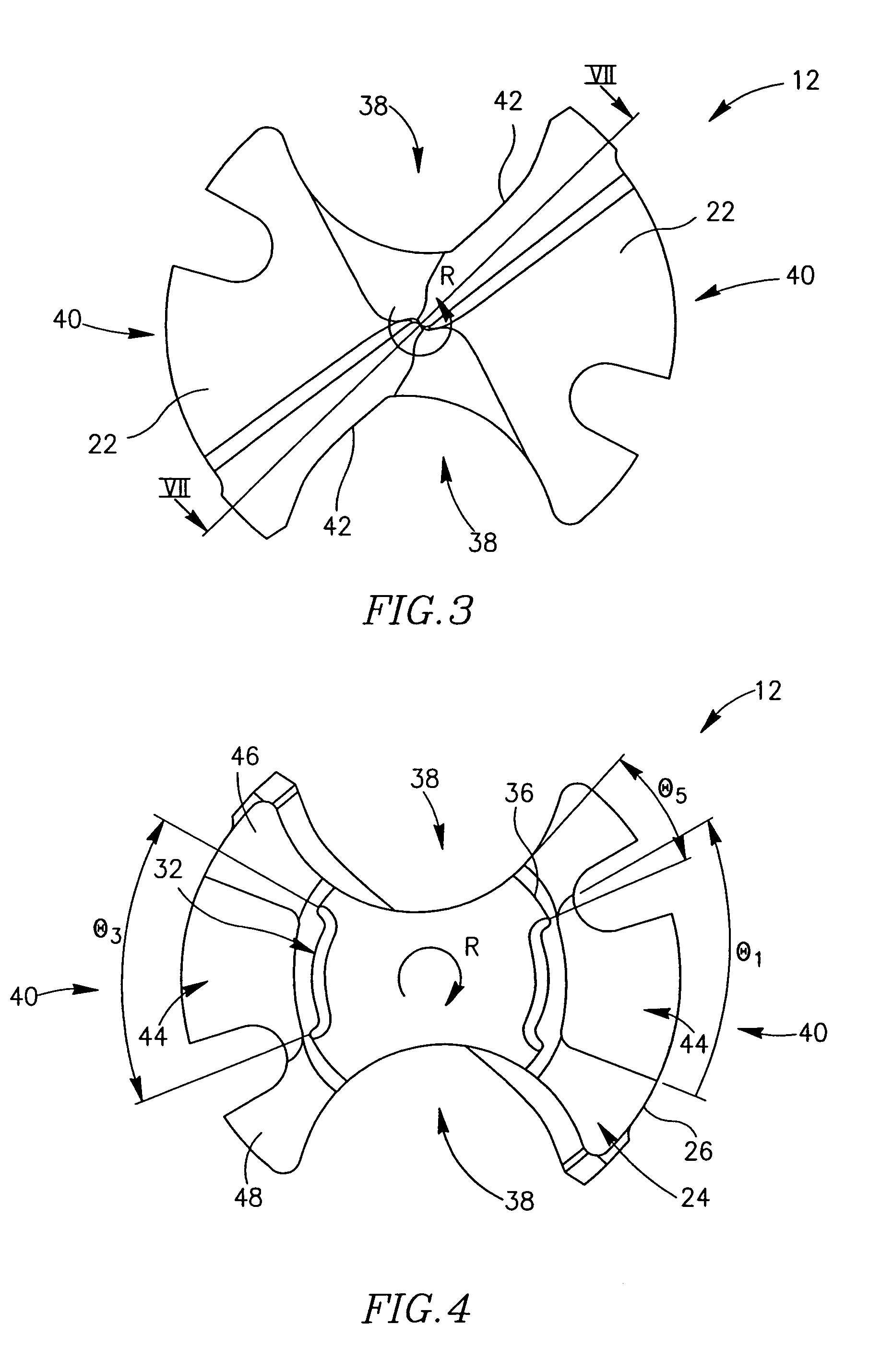
[0034]The cutting head 12 (FIG. 2) comprises a cap portion 18 and a fixation portion 20. The cap portion 18 comprises a head surface 22, a head base surface 24 transverse to the axis of rotation 16 and a peripheral side surface 26 extending therebetween. The fixation portion 20 protrudes rearwardly from the head base surface 24 away from the head surface 22 and has a head fixation surface 28 that extends circumferentially relative to the axis of rotation 16. The head fixation surface 28 (FIG. 7) extends rearwardly away from the head base surface 24 and ou...


PUM

PropertyMeasurementUnit
axis of rotationaaaaaaaaaa
cone angle β1aaaaaaaaaa
cone angle β2aaaaaaaaaa

Abstract

A drill in which a cutting head is releasably mounted on a tool shank. The cutting head is axially supported by the tool shank at four spaced apart axial support regions on shank support surfaces.

Description

FIELD OF THE INVENTION[0001]The current invention relates to a rotary cutting tool in general and a drill in particular having a releasably mounted cutting head.BACKGROUND OF THE INVENTION[0002]Such a rotary cutting tool is disclosed in U.S. Pat. No. 5,957,631. The cutting tool comprises a cutting head and tool shank each having two coupling portions and two chip flutes defined therebetween. Each coupling portion of the cutting head and tool shank has a stepped configuration with a raised base surface adjacent one flute and a lowered base surface adjacent the other flute. If the cutting head and tool shank are designed to be coupled together with both the raised and lowered base surfaces in contact, then these surfaces have to be manufactured such that the distance between them is the same to within a high degree of accuracy. If on the other hand, the cutting head and tool shank are designed to be coupled together with only one of the raised and lowered base surfaces in contact, the...

Claims


Application Information

Patent Timeline
Patent Type & Authority Patents(United States)
IPC IPC(8): B23B51/02B23B51/00
CPCB23B51/00B23B2205/02B23B2251/02B23B2251/50Y10S408/713Y10T408/03Y10T408/9098Y10T408/907Y10T408/36B23B51/02
Inventor HECHTCHEN, DANNY
Owner ISCAR LTD
Features
  • R&D
  • Intellectual Property
  • Life Sciences
  • Materials
  • Tech Scout
  • Unparalleled Data Quality
  • Higher Quality Content
  • 60% Fewer Hallucinations
Learn More