Core sample extraction system

a sampling system and core sample technology, applied in the field of new soil sampling devices, can solve the problem of not providing a means for removing soil samples

Inactive Publication Date: 2008-06-03
VANEARDEN DAVID L
View PDF13 Cites 19 Cited by
  • Summary
  • Abstract
  • Description
  • Claims
  • Application Information

AI Technical Summary

Problems solved by technology

U.S. The prior art commonly teaches the use of a sampler that retrieves a soil sample but does not provide a means for removing the soil sample from sampler.

Method used


Image

  • Core sample extraction system
  • Core sample extraction system
  • Core sample extraction system

Examples


Embodiment Construction

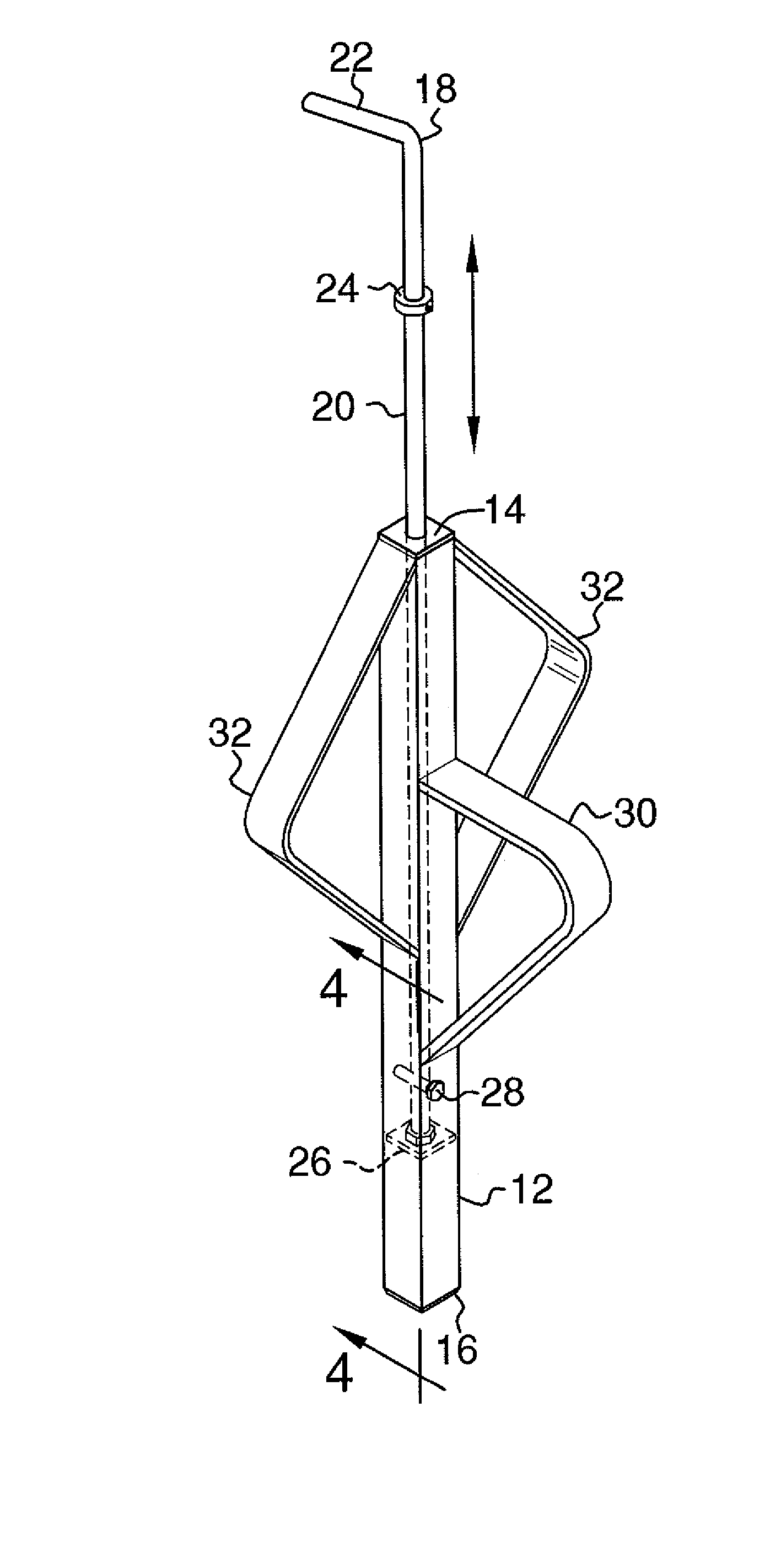
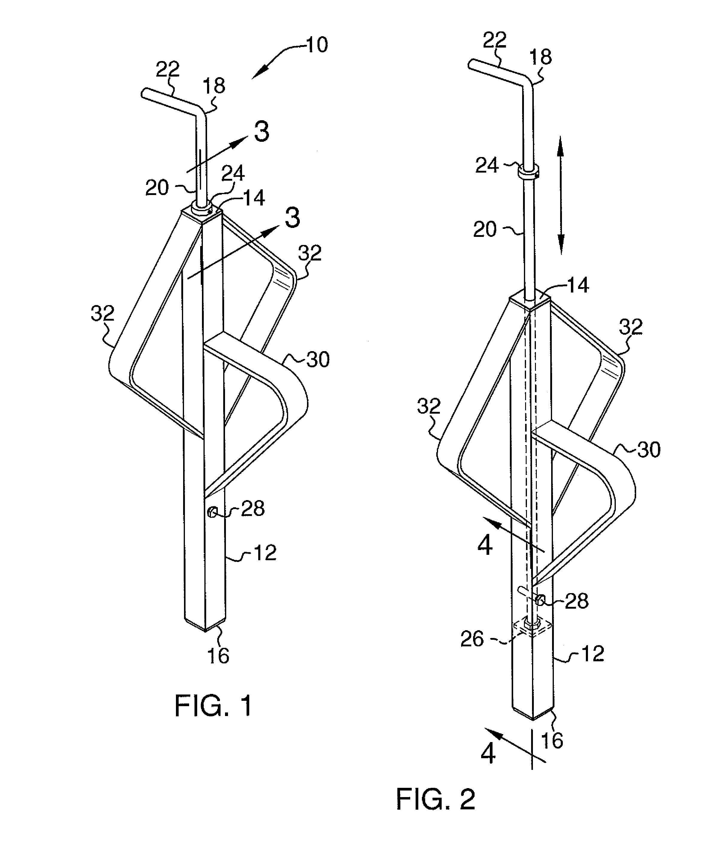
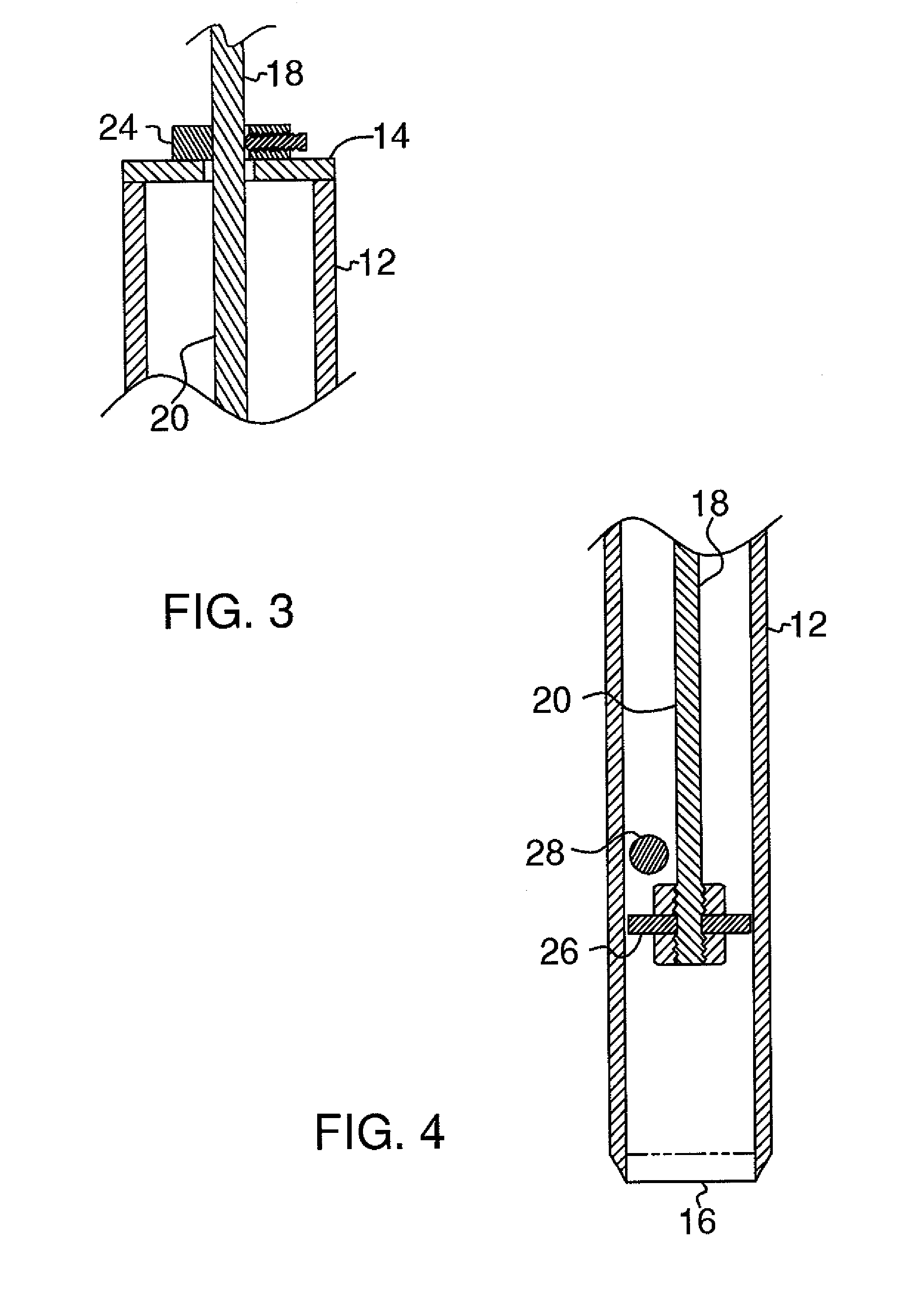
[0019]With reference now to the drawings, and in particular to FIGS. 1 through 10 thereof, a new soil sampling device embodying the principles and concepts of the present invention and generally designated by the reference numeral 10 will be described.

[0020]As best illustrated in FIGS. 1 through 10, the core sample extraction system 10 generally comprises a boring tube 12 including a top end 14 and a bottom end 16. The bottom end 16 is driven into soil to isolate a plug 1 of the soil when a mallet 2 strikes the boring tube 12. An extraction assembly 18 is positioned in the boring tube 12. The extraction assembly 18 engages the plug 1 in the boring tube 12 and pushes the plug 1 out of the bottom end 16 when the extraction assembly 18 is forced through the boring tube 12. A drive rod 20 extends into the boring tube 12 through the top end 14 of the boring tube 12. A protruding end 22 of the drive rod 20 is actuated to advance the drive rod 20 into the boring tube 12 and force the plug ...


PUM


Abstract

A core sample extraction system for extracting a plug from soil and removing the plug from the device so that the soil and any roots in the plug can be analyzed includes a boring tube including a top end and a bottom end. The bottom end is driven into soil to isolate a plug of the soil when the boring tube is struck by a mallet. An extraction assembly is positioned in the boring tube. The extraction assembly engages the plug in the boring tube and pushes the plug out of the bottom end when the extraction assembly is forced through the boring tube.

Description

BACKGROUND OF THE INVENTION[0001]1. Field of the Invention[0002]The present invention relates to soil sampling devices and more particularly pertains to a new soil sampling device for extracting a plug from soil and removing the plug from the device so that the soil and any roots in the plug can be analyzed.[0003]2. Description of the Prior Art[0004]The use of soil sampling devices is known in the prior art. U.S. The prior art commonly teaches the use of a sampler that retrieves a soil sample but does not provide a means for removing the soil sample from sampler. While these devices fulfill their respective, particular objectives and requirements, the need remains for a system that has certain improved features that provide for an extraction assembly to remove a plug of soil from the system once the plug has been retrieved by the system. Additionally, a support sleeve can be used to support the system over a bucket to allow the plug to be deposited into the bucket when the plug is e...

Claims


Application Information

Patent Timeline
Patent Type & Authority Patents(United States)
IPC IPC(8): E21B49/02
CPCA01B1/16E02D1/04G01N1/08
Inventor VANEARDEN, DAVID L.
Owner VANEARDEN DAVID L
Why Eureka
Try Eureka