Hole bottom freezing cord coring drill and coring method thereof

A core drilling tool and hole bottom technology, which is applied in the direction of extracting the undisturbed core device, earthwork drilling, etc., can solve the problems of poor effect, long drilling time, heavy workload, etc., and achieve improved recovery rate, good freezing effect, The effect of quick freezing

Inactive Publication Date: 2010-10-20
JILIN UNIV
View PDF5 Cites 52 Cited by
  • Summary
  • Abstract
  • Description
  • Claims
  • Application Information

AI Technical Summary

Benefits of technology

This technology allows for quicker cooling without damaging or affecting the structure inside hydrocarbon reserves (HCO). By combining ice crystals from liquids into solid particles instead of gas) it provides better results compared to traditional methods like vacuum extraction. Additionally, this method avoides rotating parts that could cause harm if used frequently while drillings through sedimentary rocks filled holes.

Problems solved by technology

Technological Problems In this patented technical problem addressed in the patents are how to efficiently create stable gamma ray hydrocarbon (NGH) sample from naturally occurring sources like shale deposits without decompositing them overtime due to factors including environmental conditions. Current methods involve either wet sand blasting or rotating cutting tools, but each suffers certain drawbacks.

Method used


Image

  • Hole bottom freezing cord coring drill and coring method thereof
  • Hole bottom freezing cord coring drill and coring method thereof
  • Hole bottom freezing cord coring drill and coring method thereof

Examples


Embodiment 1

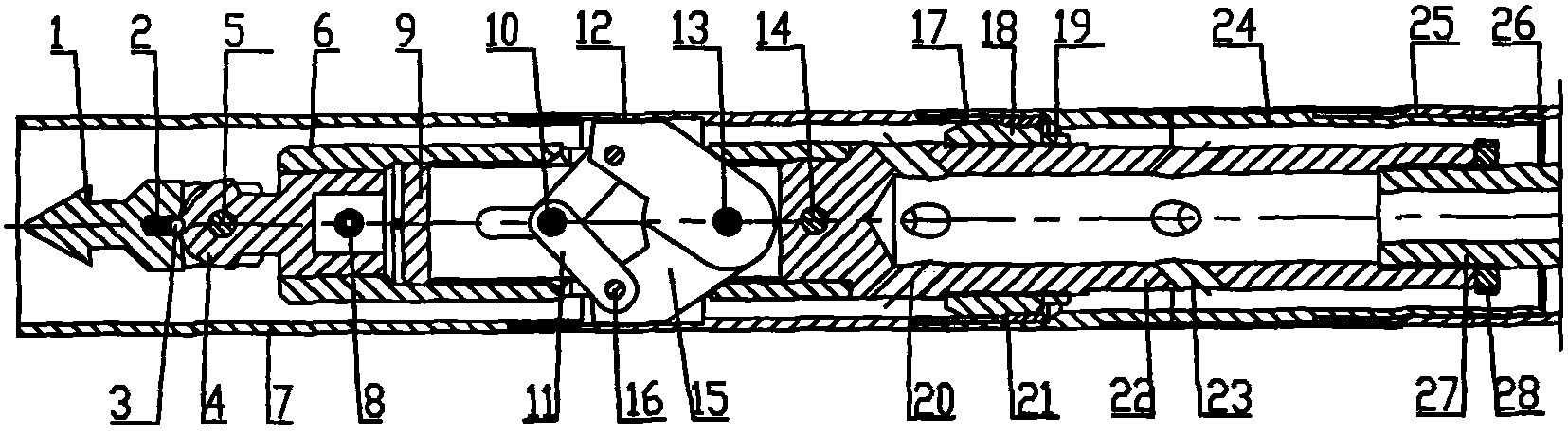
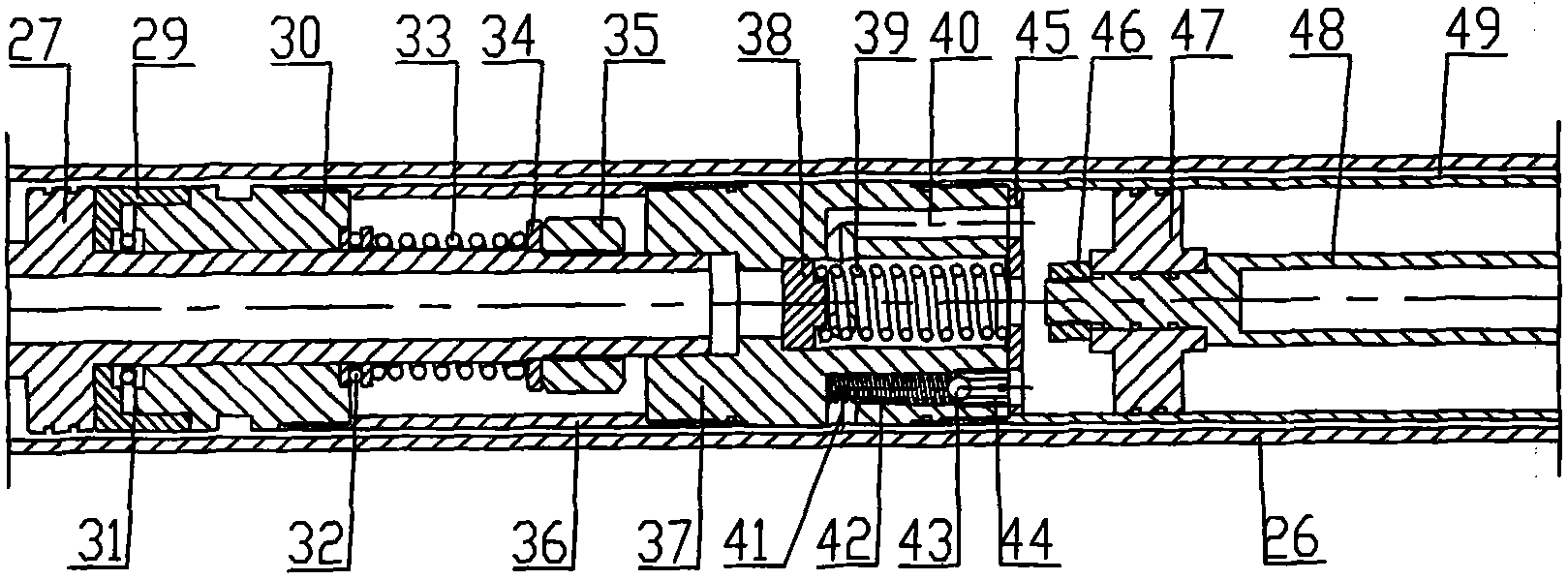
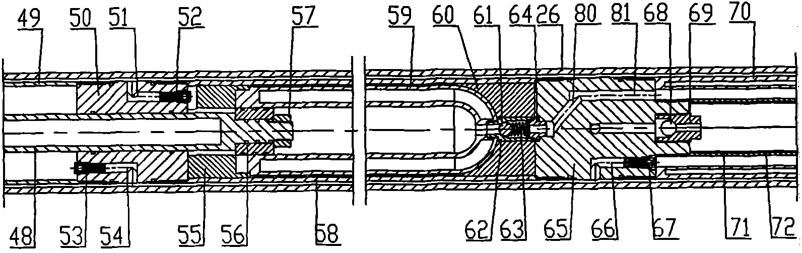
[0033] Hole Bottom Frozen Wireline Coring Tools

[0034] First assemble the outer tube assembly: the cartridge chamber 12 is threadedly connected with the cartridge stop head 7, the upper part of the inner spline short 17 is threadedly connected with the cartridge chamber 12, the lower end is threadedly connected with the inner spline 25, and the inner spline 25 is connected with the outer The spline 24 fits through the spline, and the outer spline 24 slides in the axial direction. The steps on the inner wall of the inner spline 25 and the outer wall of the outer spline 24 limit the sliding distance of the outer spline 24 in the axial direction. The outer spline 24 passes through the screw thread. Connect the outer tube 27, the guide ring 73 is embedded in the inner wall of the lower end of the outer tube 26, the reamer 74 is connected to the thread at the lower end of the outer tube 26, and the guide ring 73 is pressed tightly, and the lower end of the reamer 74 is connected t...

Embodiment 2

[0048] Hole Bottom Frozen Wireline Coring Tools

[0049] First assemble the outer tube assembly: the cartridge chamber 12 is threadedly connected with the cartridge stop head 7, the upper part of the inner spline short 17 is threadedly connected with the cartridge chamber 12, the lower end is threadedly connected with the inner spline 25, and the inner spline 25 is connected with the outer The spline 24 fits through the spline, and the outer spline 24 slides in the axial direction. The steps on the inner wall of the inner spline 25 and the outer wall of the outer spline 24 limit the sliding distance of the outer spline 24 in the axial direction. The outer spline 24 passes through the screw thread. Connect the outer tube 27, the guide ring 73 is embedded in the inner wall of the lower end of the outer tube 26, the reamer 74 is connected to the thread at the lower end of the outer tube 26, and the guide ring 73 is pressed tightly, and the lower end of the reamer 74 is connected t...


PUM


Abstract

The invention relates to a hole bottom freezing cord coring drill and a coring method thereof. In the invention, liquid nitrogen is taken as a refrigerant; the liquid nitrogen absorbs heat in the gasification process so as to freeze a core at a hole bottom and inhibit a natural gas hydrate from being decomposed. The drill comprises an outer tube assembly and an inner tube assembly; and in the process of acquiring the core, a sand hitch is utilized to drag the inner tube assembly out from the outer tube assembly, an end cover and a clamp spring are dismounted, a semi-closed tube and a core sample are pumped out together from a core tube, the two ends of the semi-closed tube are sealed by rubber plugs, and the core sample and the semi-closed tube are stored in a liquid nitrogen hold-up vessel or a high-pressure container together. The invention has the advantages that rapid freezing can be realized, and the freezing effect is good; since cord coring and hole bottom freezing are combined, rapid coring without lifting the drill is achieved; in the drilling process, the inner tube assembly does not rotate, thus damages on a hydras core caused by mechanical force generated by rotation of the drill is avoided to a greater degree, the percentage of coring, the core integrity degree and the representativeness are more effectively improved; and semi-closed tube type rapid ground surfacesampling is adopted, thus the core can be rapidly obtained from the ground surface.

Description


Claims


Application Information

Patent Timeline
Owner JILIN UNIV
Why Eureka
Try Eureka