Electrical fitting with internal cable retainer

a technology of internal cable retainer and electrical fitting, which is applied in the direction of electrical apparatus, substation/switching arrangement details, coupling device connections, etc., can solve the problems of mechanical complexity and relatively high production cost of electrical fitting, and achieve the effect of improving the ability of electrical fitting and widening the width

Active Publication Date: 2008-06-03
ARLINGTON INDS
View PDF17 Cites 15 Cited by
  • Summary
  • Abstract
  • Description
  • Claims
  • Application Information

AI Technical Summary

Benefits of technology

[0009](3) The cable retaining tang is of greater width and includes a wider cable gripping surface, thereby improving the ability of the electrical fitting to securely grip electrical

Problems solved by technology

Although the prior art split ring adequately performed the function of gripping a cable, as a result of

Method used


Image

  • Electrical fitting with internal cable retainer
  • Electrical fitting with internal cable retainer
  • Electrical fitting with internal cable retainer

Examples


Embodiment Construction

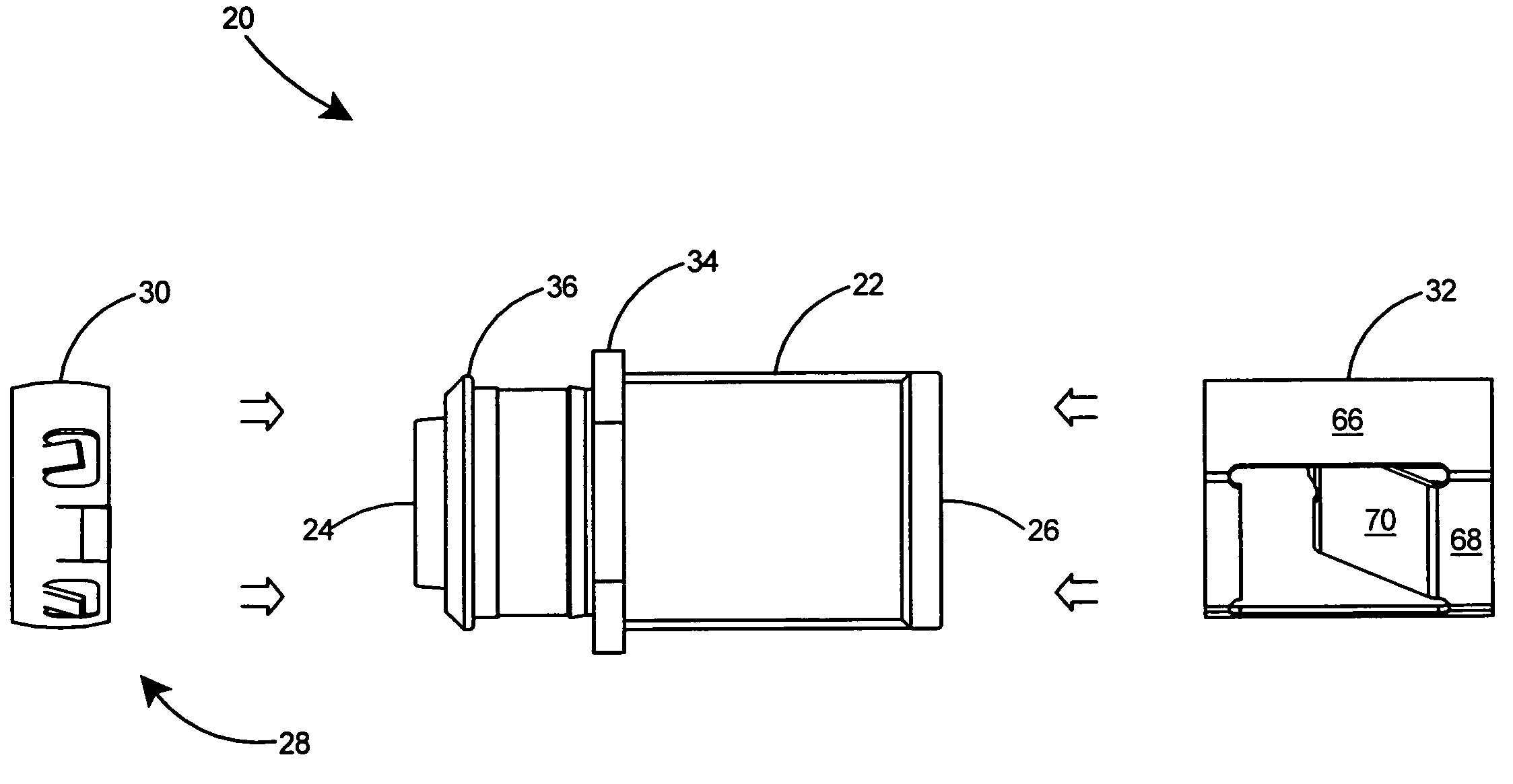
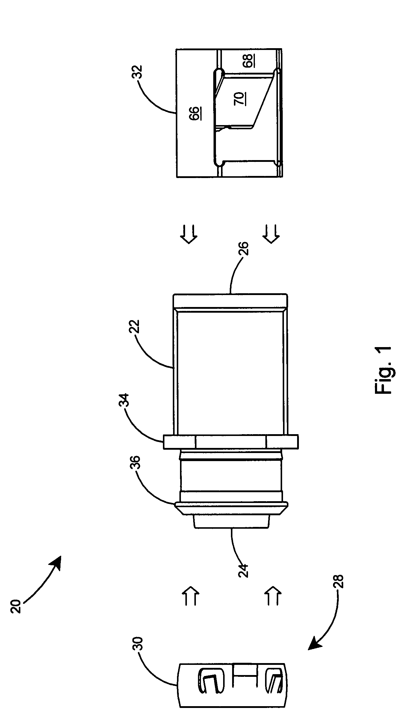
[0033]With reference to FIG. 1 there is shown a preferred embodiment of the present invention, an electrical fitting 20 having an improved arrangement for the securing of electrical cables thereto. The preferred embodiment of the electrical fitting 20 includes a connector body 22 including a leading end 24 and a trailing end 26. A fastening arrangement 28 on the leading end 24 of the connector body 22 includes a cylindrical snap ring 30 for securing the connector body 22 to a panel (not shown). A cable retainer 32 is inserted within the trailing end 26 of the connector body 22 to form the electrical fitting 20 of the present invention.

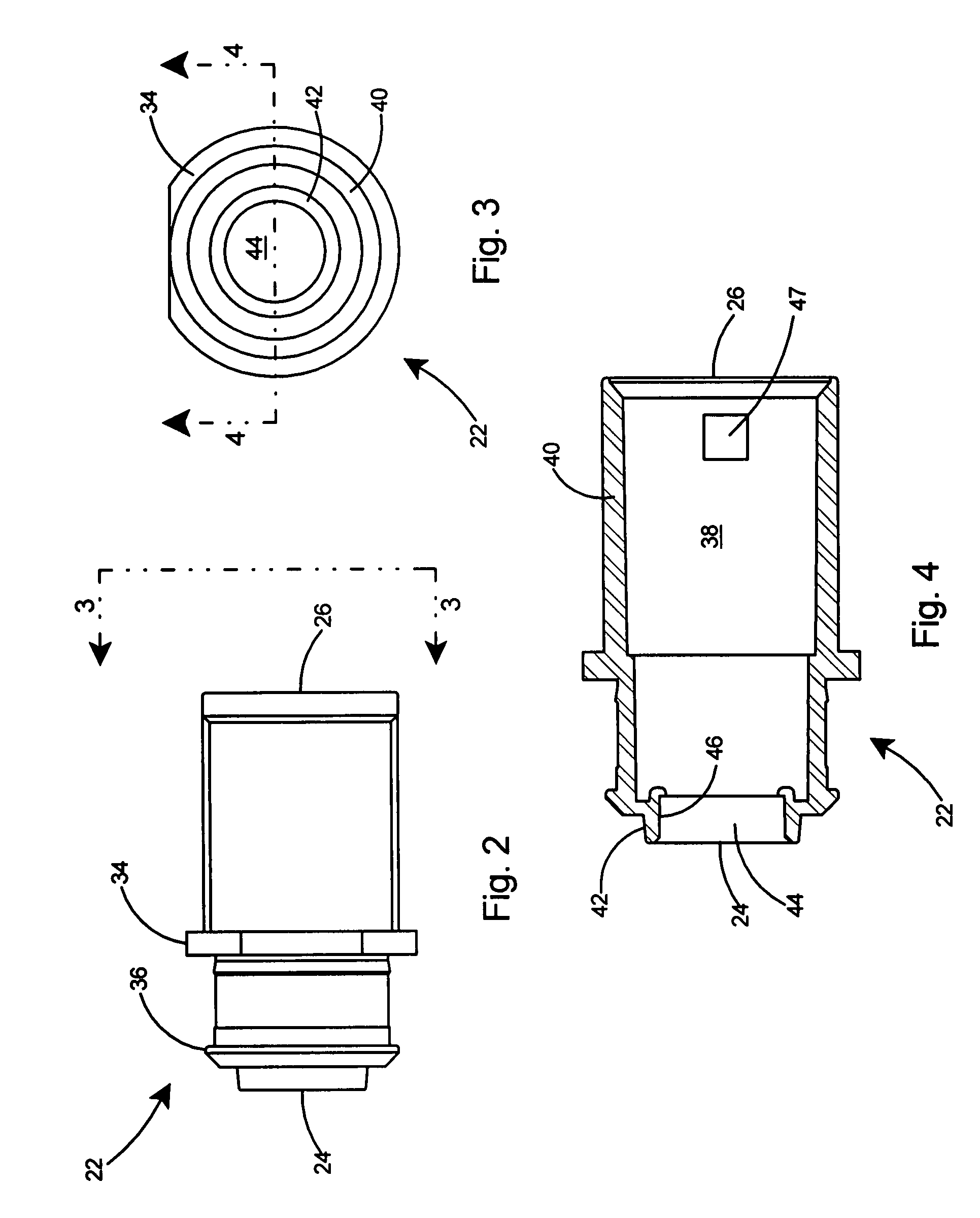
[0034]With reference to FIGS. 2-4, the connector body 22 includes a central flange 34 between the trailing end 26 and the leading end 24, an end flange 36 on the leading end 24, and a cavity 38 including a surrounding wall 40 in the trailing end 26. The connector body 22 further includes a partial closure 42 on the leading end 24, an opening 44 in the ...


PUM


Abstract

An electrical fitting having an improved arrangement on the trailing end for securing electrical cables thereto. A connector body having a cavity in the trailing end includes a cable retainer secured therein. The cable retainer includes a substantially tubular body and is constructed of spring steel. The tubular body includes a flat portion and an arcuate portion. A single cable retaining tang extends inwardly from the flat portion. Providing the cable retaining tang on the flat portion of the tubular body enables a straight bend line between the cable retaining tang and the tubular body, thereby allowing the tang to flex easily. The cable retaining tang includes a wide cable gripping surface to enable secure gripping of an electrical cable as it is inserted within the trailing end of the fitting.

Description

FIELD OF THE INVENTION[0001]This invention relates to fittings for connecting electrical cables to a panel and specifically to an electrical fitting having an improved arrangement on the trailing end for receiving an electrical cable or conduit.BACKGROUND OF THE INVENTION[0002]Electrical fittings are commonly used to connect electrical cables to electrical panels or boxes. In recent years, snap fit electrical fittings have become increasingly popular.[0003]Several prior art connectors have been proposed for the attachment of electrical cables or conduits to panels or electrical boxes. Some of these, such as that shown in U.S. Pat. No. 6,335,488 to Gretz, include a tubular body with a cavity on the trailing end and a cylindrical-shaped split ring that is inserted into the cavity. The prior art split ring included a plurality of cable gripping tangs extending inwards of the cylindrical ring for securing a cable to the trailing end of the connector. Although the prior art split ring ad...

Claims


Application Information

Patent Timeline
IPC IPC(8): H01R13/73
CPCH01R13/5804H01R13/745H01R13/746H02G3/0691
Inventor GRETZ, THOMAS J.
Owner ARLINGTON INDS
Why Eureka
Try Eureka