System, a tool and method for communicating with a faulted circuit indicator using a remote display

a faulted circuit and remote display technology, applied in the field of underground electrical power line monitoring, maintenance, and system maintenance, can solve the problems of beacon bolt, reed switch, and fci may not include an fci microcontroller,

Active Publication Date: 2008-06-03
SCHWEITZER ENGINEERING LABORATORIES
View PDF24 Cites 98 Cited by
  • Summary
  • Abstract
  • Description
  • Claims
  • Application Information

AI Technical Summary

Problems solved by technology

In some cases however, the FCI may not include an FCI microcontroller.
As a result, the ⅝″ remote display mounting hole required by the beacon bolt of the '478 patent has rendered use of the beacon bolt, with its reed switch, less desirable due to both its physical size and increased difficulty driving magnetic flux from the magnetic test tool through the beacon bolts.

Method used


Image

  • System, a tool and method for communicating with a faulted circuit indicator using a remote display
  • System, a tool and method for communicating with a faulted circuit indicator using a remote display
  • System, a tool and method for communicating with a faulted circuit indicator using a remote display

Examples


Embodiment Construction

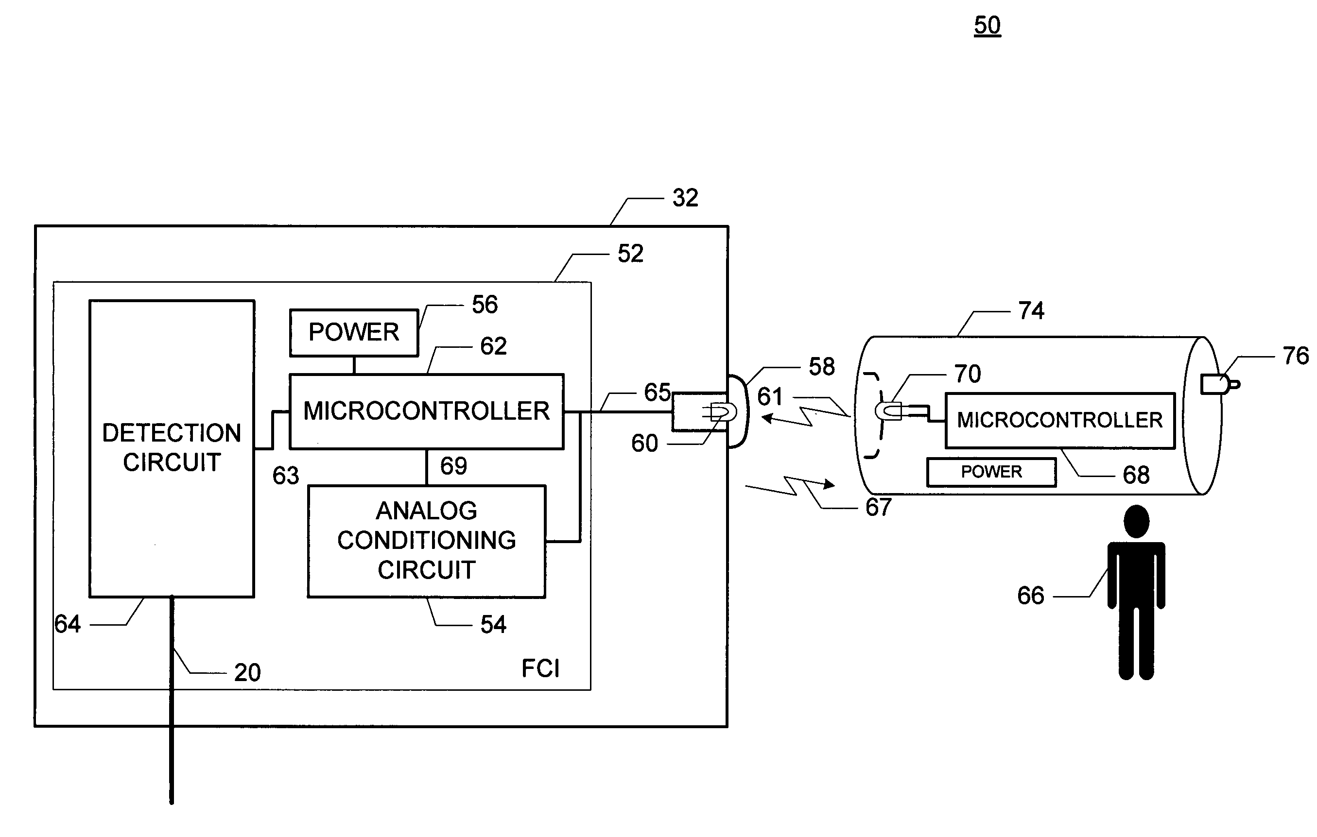
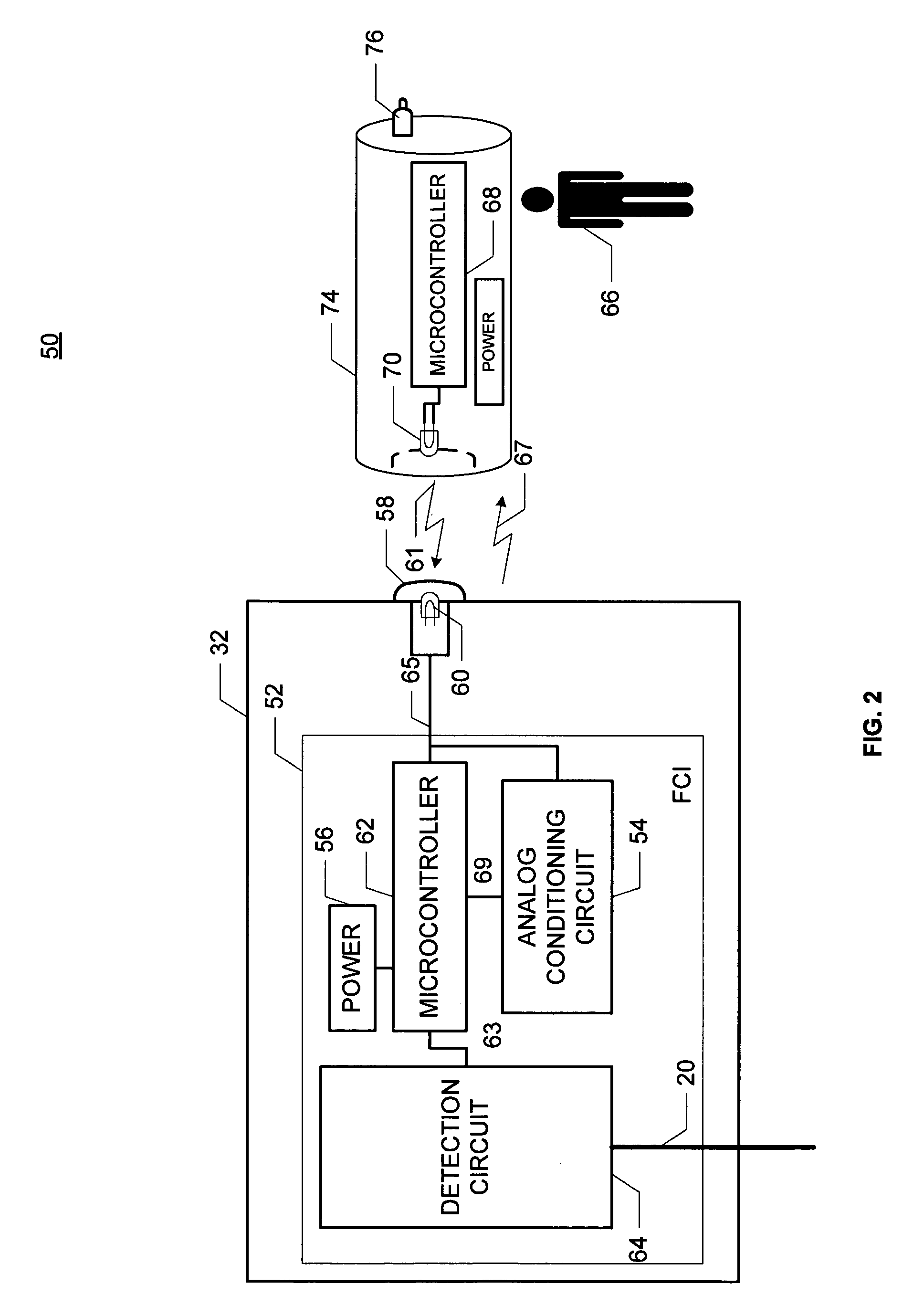
[0027]Implementation of the system, the tool and the method disclosed herein enables utility personnel outside of an enclosure housing the FCI to transmit optical serial communications affecting FCI operation via a remote display. The remote display is located within a display bolt mounted in an enclosure wall, thereby precluding a need to physically access the FCI located in the enclosure's interior. Unlike prior art remote displays having both a reed switch and an LED, and requiring a ⅝″ display mounting hole, the remote display of the system and method disclosed herein includes only the LED and therefore requires a smaller remote display mounting hole. In addition, a user command tool of the system and method disclosed herein is capable of transmitting optical serial data and optical serial commands (i.e., optical serial communications) to the FCI via the LED, resulting in more robust capability to reset, test and maintain the FCI. Although discussed in terms of underground power...


PUM


Abstract

Provided is a system, a tool and a method for communicating with a faulted circuit indicator (FCI), the faulted circuit indicator including a detection circuit for monitoring an electrical conductor of a power system. The system includes a remote display mounted in a wall of an enclosure and visible from outside of the enclosure and a first light emitting diode associated with the remote display. The first light emitting diode generates an optical FCI status signal in response to an occurrence of a fault in the electrical conductor. The system also includes a first microcontroller operatively coupled to the remote display and the detection circuit, and a handheld user command tool adapted to optically couple with the remote display. The handheld user command tool is also adapted to generate an optical serial communication. The optical serial communication provides data and commands for operation of the faulted circuit indicator.

Description

RELATED APPLICATIONS[0001]NoneBACKGROUND OF THE INVENTION[0002]1. Field of the Invention[0003]The invention relates generally to the monitoring, servicing, and maintaining of underground electrical power lines and more specifically to a system, a tool and a method for communicating with a faulted circuit indicator using a remote display.[0004]2. Description of Related Art[0005]Faulted Circuit Indicators (FCIs) indicate the occurrence of a fault current in a monitored electrical conductor such as a transmission line. An FCI typically includes a housing and a number of FCI elements. The FCI elements may include a power supply such as a battery, a “remote” display for indicating when a fault in a monitored electrical conductor has occurred, a detection circuit such as a reed switch or split-core current transformer for sensing the current in the monitored electrical conductor and for providing a signal that is related to the current in the monitored conductor, and an FCI microcontrolle...

Claims


Application Information

Patent Timeline
Patent Type & Authority Patents(United States)
IPC IPC(8): G08B5/00G01R31/00H04B10/00G08B21/00
CPCH04B10/1141H04B10/116
Inventor FEIGHT, LAURENCE V.
Owner SCHWEITZER ENGINEERING LABORATORIES
Why Eureka
Try Eureka