
Mounting apparatus for data storage device

a technology for mounting apparatuses and data storage devices, which is applied in the direction of electrical apparatus casings/cabinets/drawers, furniture parts, instruments, etc., can solve the problems of laborious and time-consuming, laborious and laborious installation of such devices in electronic devices, and the inability to manipulate screws

Inactive Publication Date: 2008-06-03
HONG FU JIN PRECISION IND (SHENZHEN) CO LTD +1
View PDF5 Cites 26 Cited by
  • Summary
  • Abstract
  • Description
  • Claims
  • Application Information

AI Technical Summary

Benefits of technology

The patent describes a mounting apparatus for a data storage device with a fixing hole. It includes a mounting bracket, a locking member, and an operating member. The mounting bracket has a sideboard with a through hole, and the locking member has a locking pin that engages with the data storage device's fixing hole. The locking member is pivotally connected to the mounting bracket and can be pressed by the operating member. The operating member has a resilient portion to press the locking member and a clip portion to draw it outward. The technical effect of this invention is to provide a simple and effective way to mount a data storage device securely.

Problems solved by technology

However, the installation of such devices in the electronic apparatus is usually labor-intensive.
Usually, these screws are so small that it is difficult to install them.
It is laborious and time-consuming to manipulate the screws.
Some accidental damage may occur in the computer.
However, the screws have to be removed to detach the rails from the data storage device before replacing the data storage device.

Method used


Image

  • Mounting apparatus for data storage device
  • Mounting apparatus for data storage device
  • Mounting apparatus for data storage device

Examples


Embodiment Construction

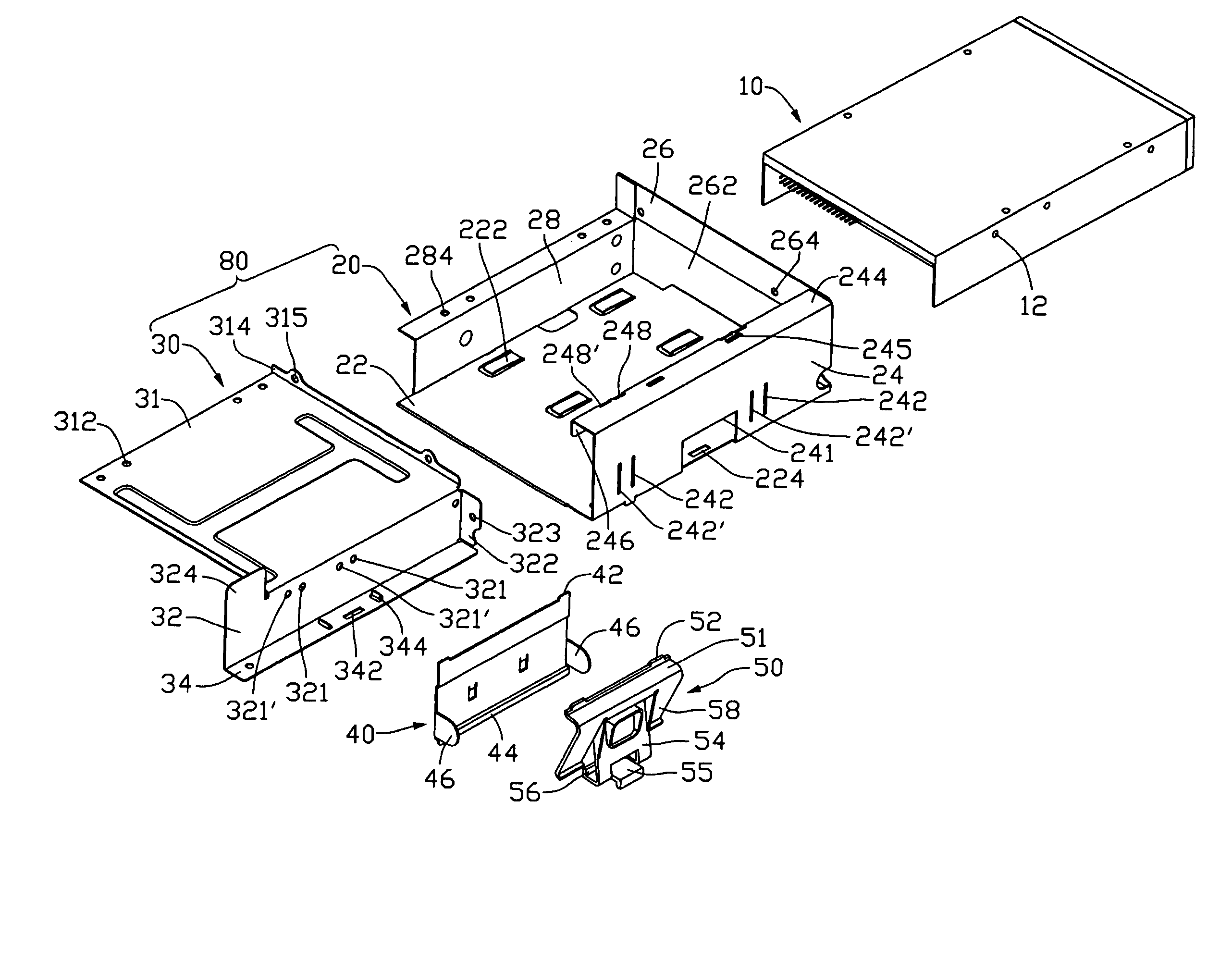
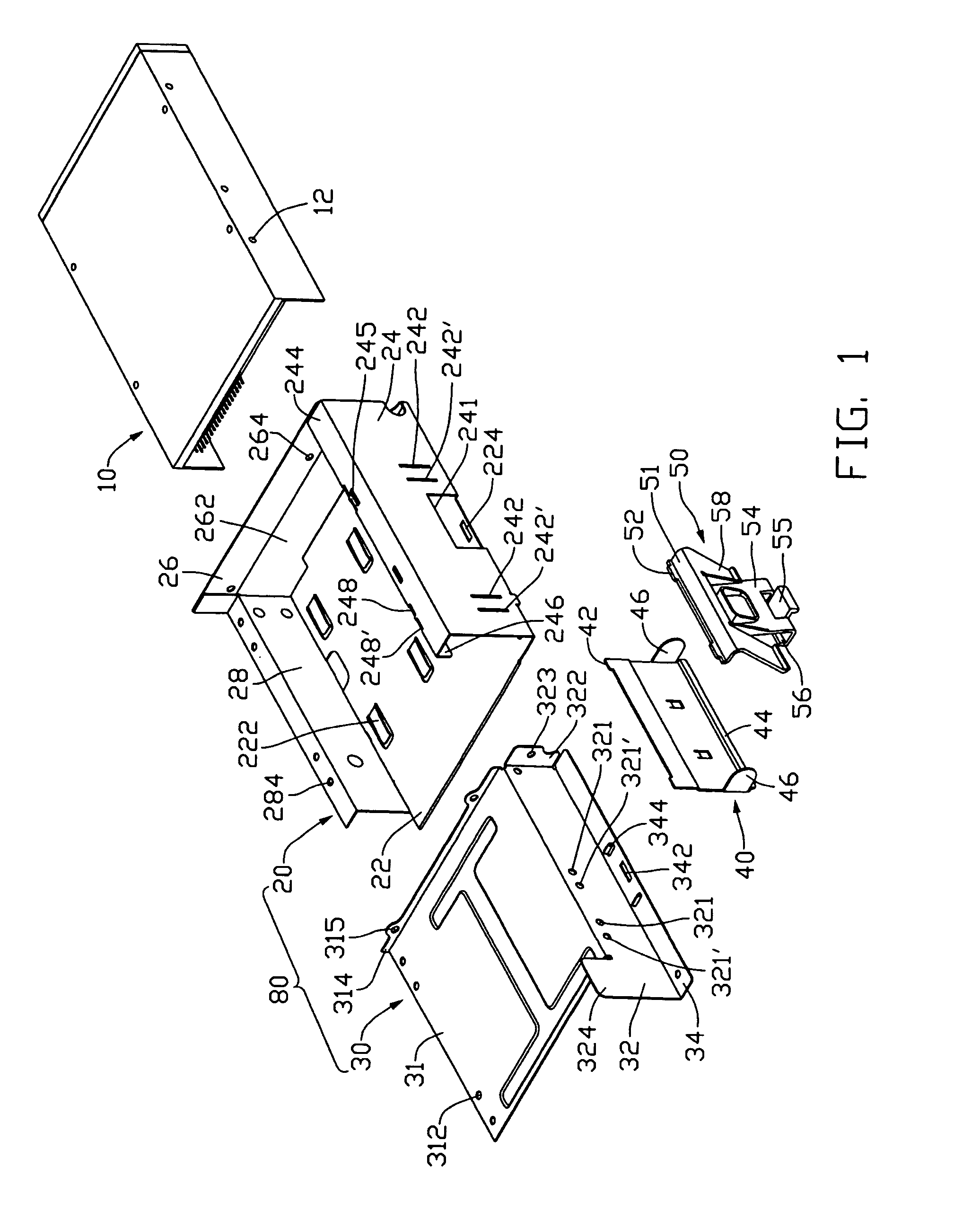
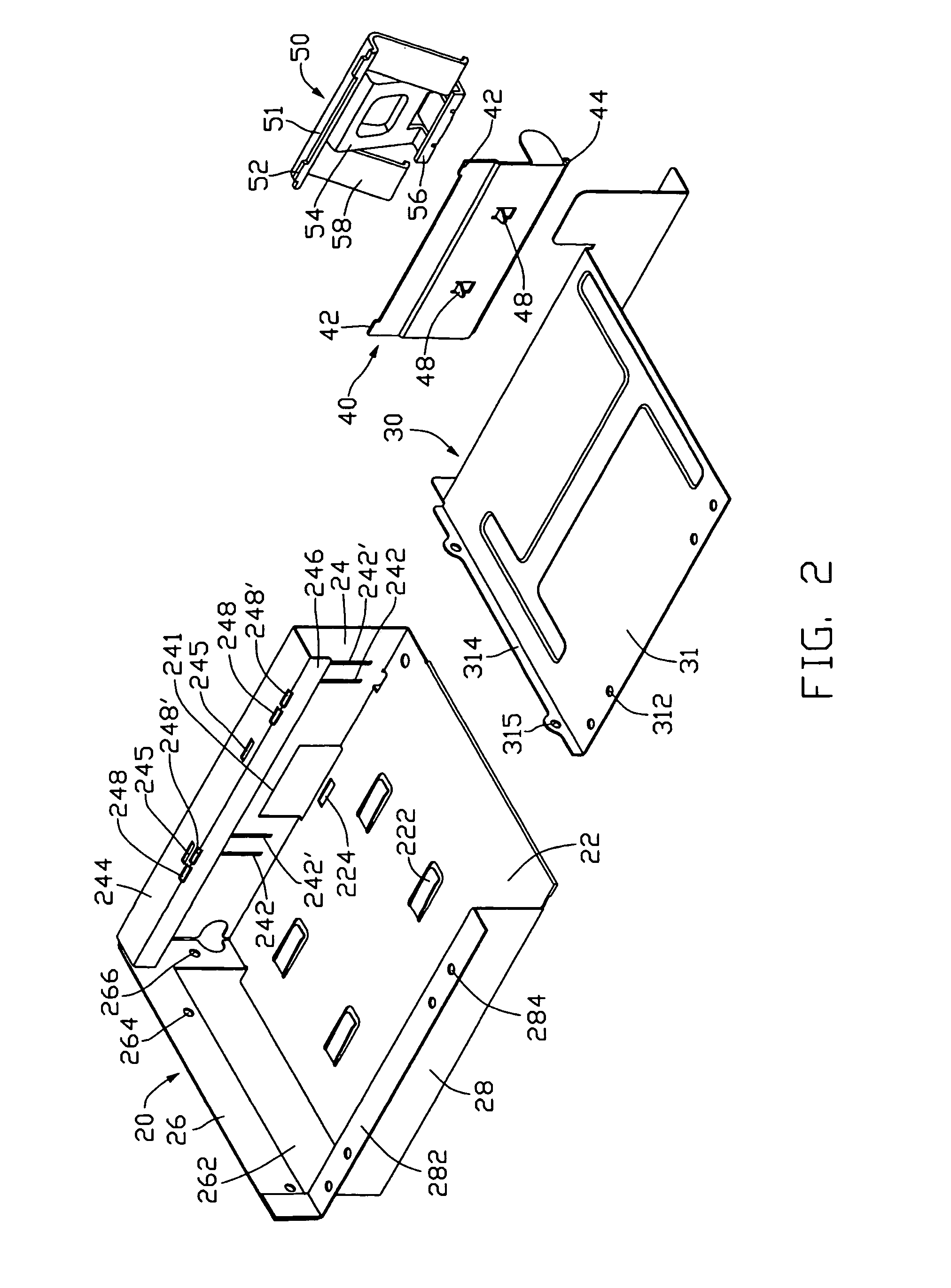
[0018]Referring to FIG. 1 to FIG. 3, in a preferred embodiment of the present invention, a mounting apparatus is provided for mounting a data storage device 10. The data storage device 10 defines two fixing holes 12 in a sidewall. The mounting apparatus includes a mounting bracket 80, a locking member 40, an operating member 50, and a plurality of fasteners, such as rivets 90 (shown in FIG. 5). The mounting bracket 80 includes a first bracket 20, and an L-shaped second bracket 30.

[0019]The first bracket 20 includes a base wall 22, a first sidewall 24 perpendicularly extending from a side of the base wall 22, and a second sidewall 26 abutting on the first sidewall 24 and perpendicularly extending from an end of the base wall 22, and a third sidewall 28 abutting on the second sidewall 26 and perpendicularly extending from an opposite side of the base wall 22. A plurality of tongue-shaped tabs 222 slantingly extends out from the base wall 22. A locating hole 224 is defined in a middle ...


PUM


Abstract

A mounting apparatus for mounting a data storage device that defines a fixing hole therein includes a mounting bracket, a locking member, and an operating member. The mounting bracket includes a sideboard, and a first sidewall. The sideboard defines a through hole therein. The locking member arranged between the sideboard and the first sidewall includes a locking pin protruding therefrom. The locking pin is inserted through the through hole of the mounting bracket and configured for engaging in the fixing hole of the data storage device. A top of the locking member is pivotably connected to the mounting bracket. The operating member is arranged between the locking member and the first sidewall, and includes a resilient portion for pressing the locking member inward, and a first clip portion for clipping a bottom of the locking member for drawing the locking member to pivot outward. A top of the operating member is pivotably connected to the mounting bracket.

Description

CROSS-REFERENCE TO RELATED APPLICATION[0001]Relevant subject matter is disclosed in the copending U.S. patent application filed on the same date with Ser. No. 11 / 592847 and having a same title with the present application, which is assigned to the same assignee with this patent application.BACKGROUND OF THE INVENTION[0002]1. Field of the Invention[0003]The present invention relates to mounting apparatuses, and more particularly to a mounting apparatus which readily allows securely installing or removing a data storage device to or from an electronic device.[0004]2. Description of Related Art[0005]An electronic apparatus, such as a computer, or a server, usually includes data storage devices, such as hard disk drives, compact disk read-only memory (CD-ROM) drives, digital video disc (DVD) drives, and floppy disk drives. These devices are typically added to increase the functionality of the electronic apparatus as desired by a user. However, the installation of such devices in the ele...

Claims


Application Information

Patent Timeline
Patent Type & Authority Patents(United States)
IPC IPC(8): G06F1/16
CPCG06F1/184G06F1/187
Inventor LIN, YANG-MINGJING, XIAO-ZHONG
Owner HONG FU JIN PRECISION IND (SHENZHEN) CO LTD
Learn More