Method, system, and program for synchronization and resynchronization of a data stream

a data stream and data synchronization technology, applied in the field of method, system and program for synchronizing and resynchronizing a data stream, can solve the problems of infinite error propagation, catastrophic type of failure, and the inability of the decoder to successfully decode the encoded data

Active Publication Date: 2003-07-03
GLOBALFOUNDRIES US INC
View PDF4 Cites 21 Cited by
  • Summary
  • Abstract
  • Description
  • Claims
  • Application Information

AI Technical Summary

Benefits of technology

0035] The synchronization mark or pattern 61 is provided to allow the sync detector 38 to determine the start of encoded data, aligning it to the codeword boundaries. Because the synchronization mark is always adjacent to a VFO pattern (as opposed to a resynchronization mark which is not), the synchronization mark is readily detected following the VFO pattern. The location of the synchronization mark largely eliminates any concern that it will be seen in encoded data.

Problems solved by technology

Accordingly, the decoder will not be able to successfully decode the encoded data unless or until some further sync field is encountered, such as the next sync or resynchronization.
Such a failure to decode may result in infinite error propagation, which is a catastrophic type of failure.
Even though the location of the VFO pattern and the synchronization mark are known, misdetection of one or more bits in the synchronization mark may prevent recognition of the synchronization mark.
Without proper recognition of the synchronization mark, the data detector will not be in-sync with the recorded data and will not recognize the data.
However, errors in the VFO or synchronizing patterns may result in missing detection of the synchronization mark or detecting it in the wrong place.
If the start of data is not determined via detection of the synchronization mark, all data between one synchronization mark and a subsequent synchronization mark which is detected successfully will be lost.
This may have a catastrophic effect, rendering useless the error correcting codes protecting the data.
However, in certain applications, such as an Enhanced Partial Response Type 4 (EPR4) waveform, the maximum Hamming distance measurements are less effective because errors tend to propagate between peaks.

Method used


Image

  • Method, system, and program for synchronization and resynchronization of a data stream
  • Method, system, and program for synchronization and resynchronization of a data stream
  • Method, system, and program for synchronization and resynchronization of a data stream

Examples


Embodiment Construction

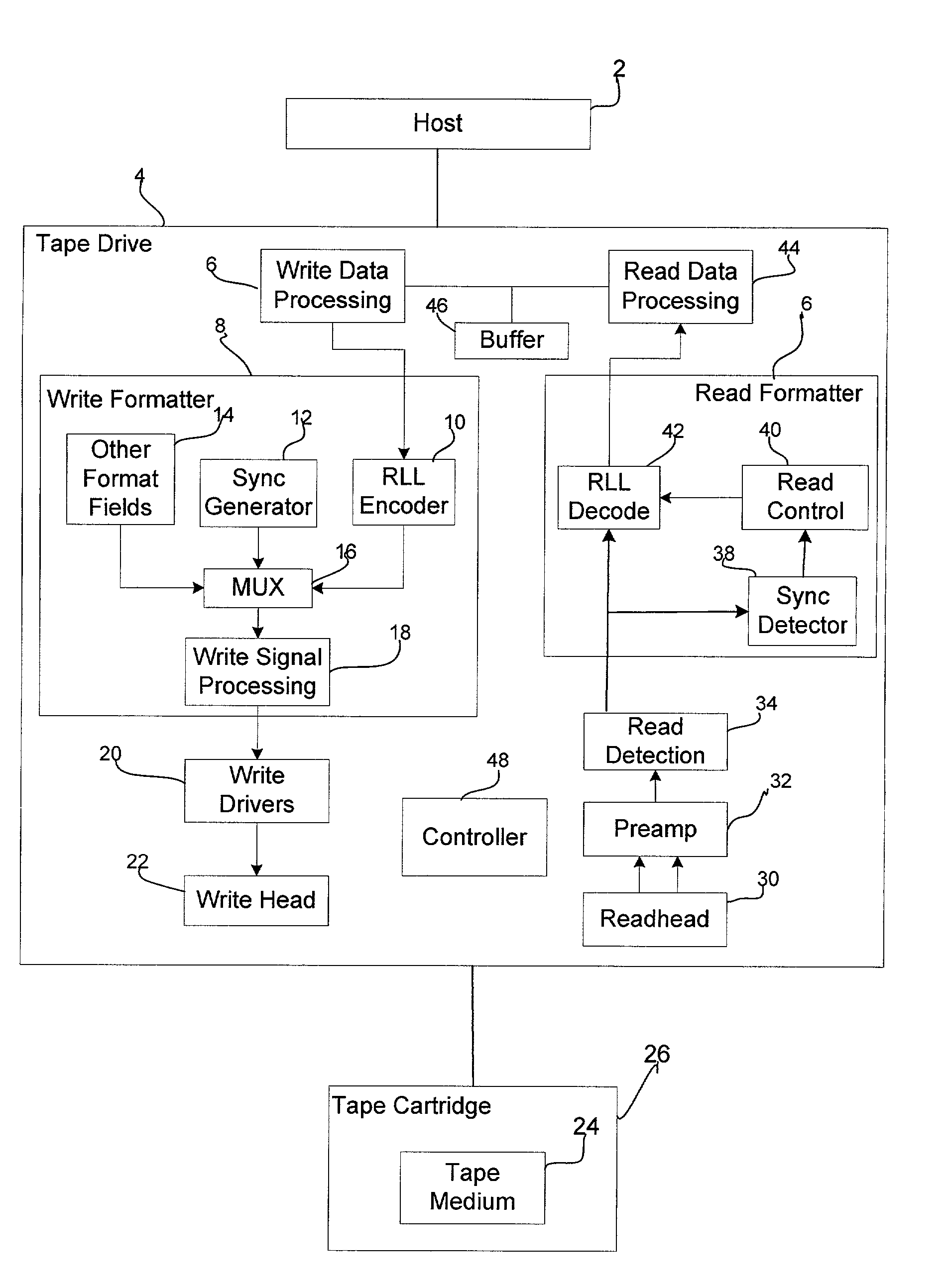
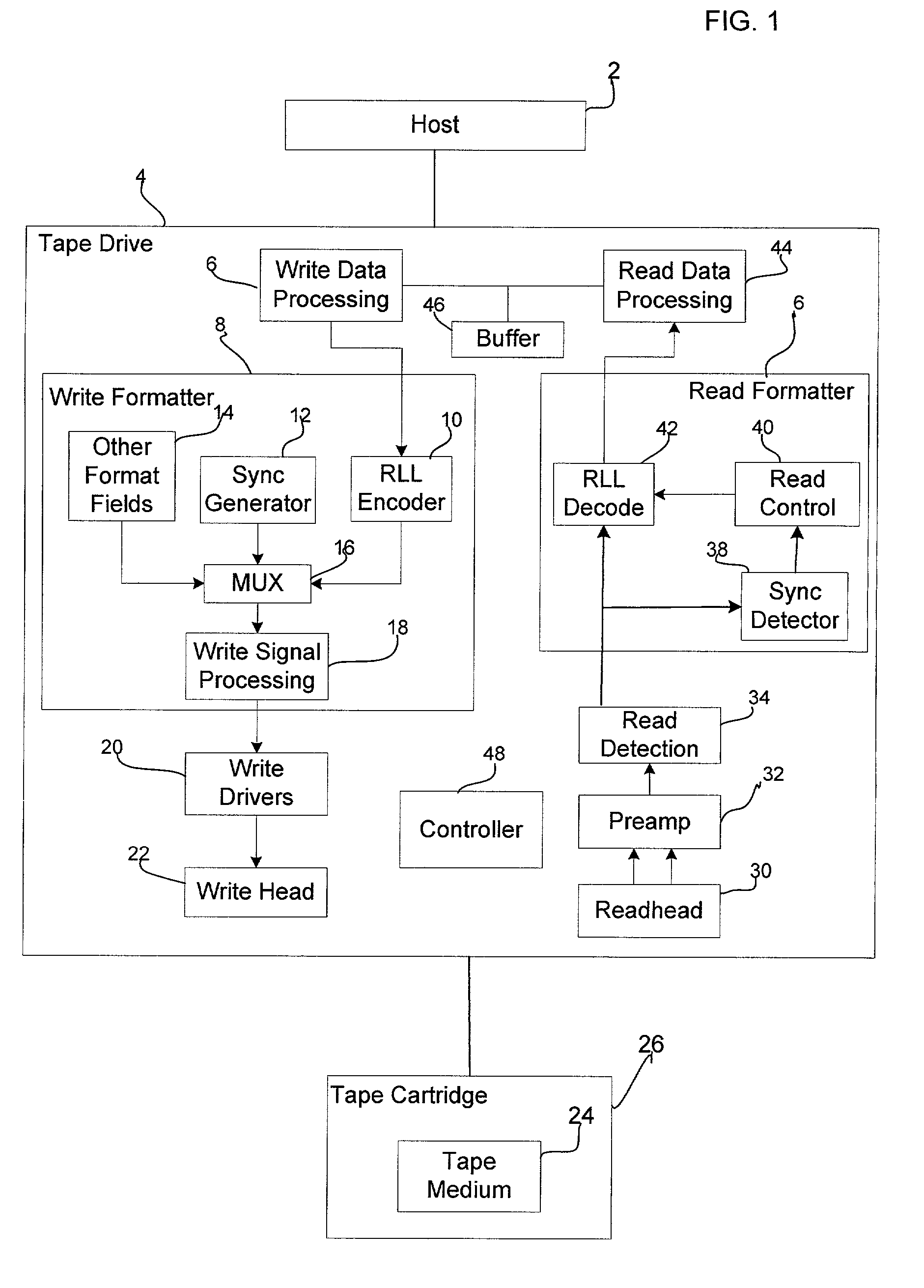
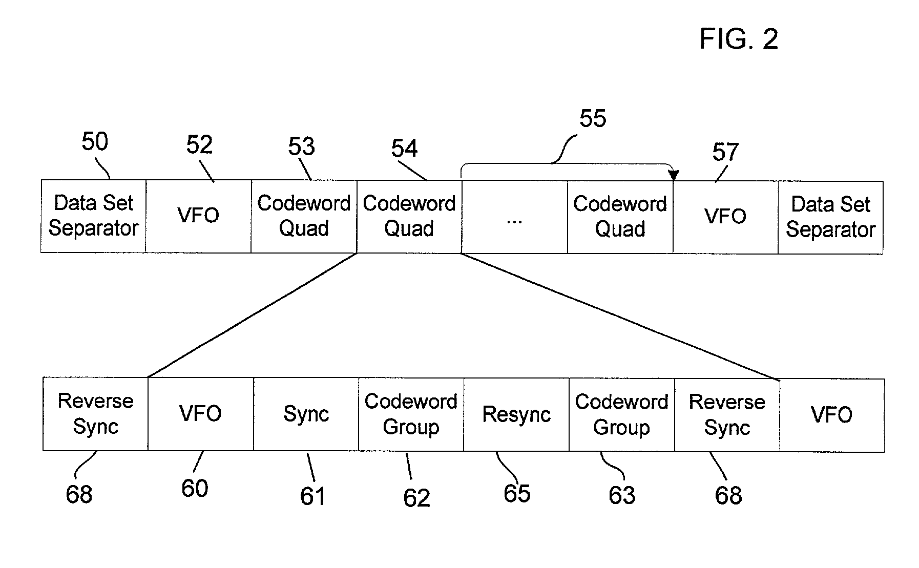
[0011] Provided is a method, system, and program for achieving synchronization in a binary data stream. A binary data stream is received. A synchronization mark having at least one isolated peak is generated into at least one point in the data stream. An encoded data stream is formed by concatenating the synchronization mark with the received binary data. During decoding, the synchronization mark is detected based on error propagation occurring adjacent to the at least one isolated peak of the synchronization mark.

[0012] In further implementations, the received binary data stream is concatenated with at least one resynchronization mark, wherein the at least one resynchronization mark is located in the middle of the received binary data stream and the resynchronization mark and the encoded binary data are different.

[0013] The resynchronization mark is detected to verify that the decoding process is operating correctly.

[0014] In still further implementations, a data section of the rec...


PUM

PropertyMeasurementUnit
transition frequencyaaaaaaaaaa
Hamming distanceaaaaaaaaaa
run lengthaaaaaaaaaa

Abstract

Provided is a method, system, and program for providing synchronization in a binary data stream. A binary data stream is received. A synchronization mark having at least one isolated peak is generated into at least one point in the data stream. An encoded data stream is formed by concatenating the synchronization mark with the received binary data. During decoding, the synchronization mark is detected based on error propagation occurring adjacent to the at least one isolated peak of the synchronization mark.

Description

[0001] This application is related to the copending and commonly assigned United States patent application entitled "Method and Apparatus for Encoding Data to Guarantee Isolated Transitions in a Magnetic Recording System", having Ser. No. ______ attorney docket no. TUC920010037US1, which patent application was filed on the same date herewith and is incorporated herein by reference in its entirety.[0002] 1. Field of the Invention[0003] The present invention relates to a method, system, and program for synchronization and resynchronization of a data stream.[0004] 2. Description of the Related Art[0005] In data recording systems, a data drive writes positive and negative "flux transitions" to a storage medium using encoding schemes known in the art, and a decoder is used to read back the encoded data stored on the storage medium. A "one" bit ("1") represents a peak or trough in the signal while a "zero" bit ("0") indicates no peak. Data to be provided to a recording channel or decoder ...

Claims


Application Information

Patent Timeline
Patent Type & Authority Applications(United States)
IPC IPC(8): G11B20/14G11B27/30
CPCG11B20/1426G11B2020/1446G11B27/3027G11B20/10
Inventor BLAUM, MARIOJAQUETTE, GLEN ALANMARCUS, BRIAN HARRYMELAS, CONSTANTIN MICHAEL
Owner GLOBALFOUNDRIES US INC
Why Eureka
Try Eureka