
Electronic whiteboard system eraser

a technology of eraser and eraser surface, which is applied in the field of electronic whiteboard system eraser, can solve the problems of data integrity problems, difficult for electronics to accurately detect where and how much of the eraser surface is actually touching the whiteboard, and the current electronic whiteboard suffers from a few serious shortcomings

Inactive Publication Date: 2002-10-31
STEELCASE INC
View PDF0 Cites 20 Cited by
  • Summary
  • Abstract
  • Description
  • Claims
  • Application Information

AI Technical Summary

Benefits of technology

The solution enables user-friendly erasing and data filtering, eliminating data recording errors by ensuring positive contact and accurate detection of erasure actions, mimicking the experience of writing on a chalkboard, while providing audible feedback for mode confirmation.

Problems solved by technology

Currently available electronic whiteboards, however, suffer from a few serious short comings.
Obviously, this time consuming and awkward process is a serious departure from the normal way erasing occurs on a typical blackboard and thus the user must be provided with detailed instructions regarding how to properly erase the stored digital information, and the audience must patiently wait for the presenter to complete all the erasing functions before the presentation can resume.
Another reason for this complex methodology is due to the fact that most erasers currently used are flat.
Since the typical user may alternately presses lightly and then more firmly and / or rock the erasure from side to side during each erase stroke, it is difficult for the electronics to accurately detect where and how much of the eraser surface is actually touching the whiteboard.
Another shortcoming in current electronic whiteboards systems is the data integrity problems which occur due to inadvertent contacts with the whiteboard.
The whiteboard electronics may accurately record the pen movement but will also erroneously record the contact of the user's hand with the whiteboard surface as a writing event.
The same type of data corruption can occur due to electronic noise generated by outside influences beyond the control of the electronics portion of the whiteboard system.
At printout or transmission, the corrupted data will thus not accurately match the actual writing on the whiteboard.

Method used


Image

  • Electronic whiteboard system eraser
  • Electronic whiteboard system eraser
  • Electronic whiteboard system eraser

Examples


Embodiment Construction

[0021] Other objects, features and advantages will occur to those skilled in the art from the following description of a preferred embodiment and the accompanying drawings, in which:

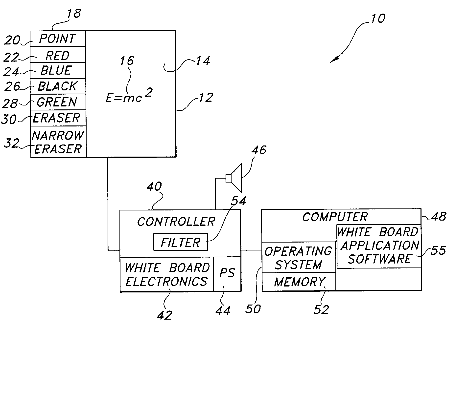
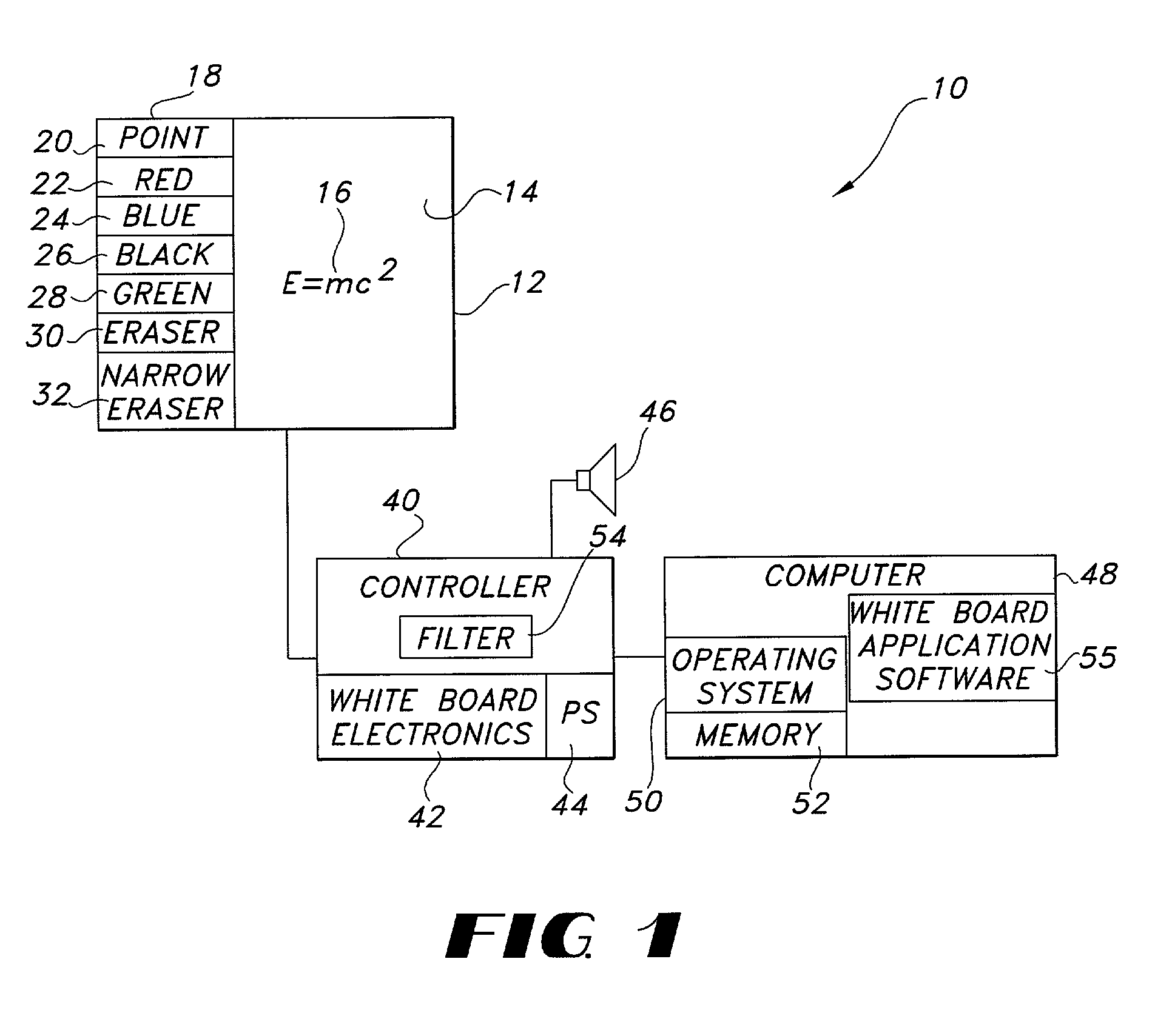
[0022] FIG. 1 is a block diagram showing the primary components of electronic whiteboard system of this invention;

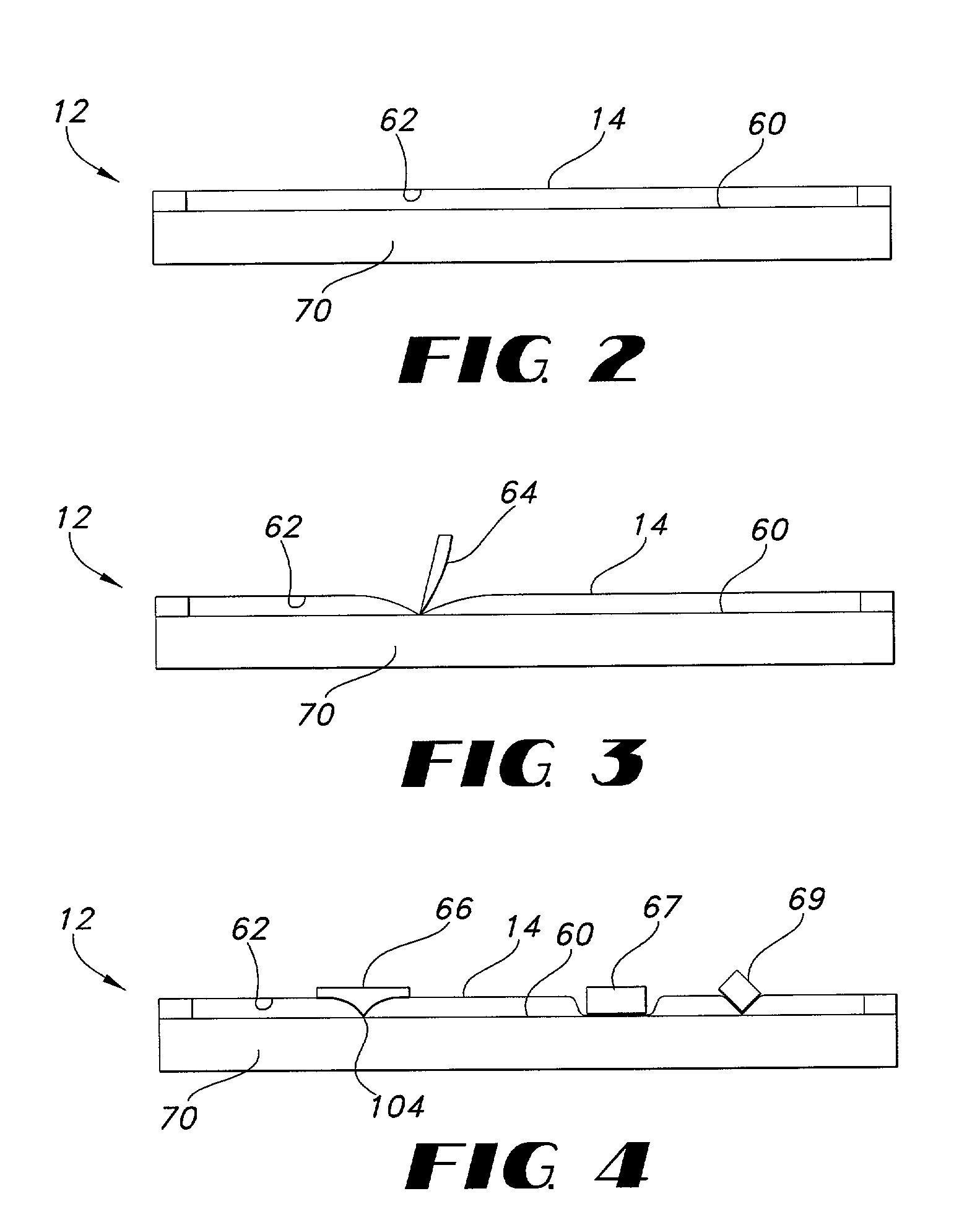
[0023] FIG. 2 is a side cutaway view of the digitizer portion of the electronic whiteboard system shown in FIG. 1;

[0024] FIG. 3 is a side cutaway view showing the use of a writing instrument such as a pen in conjunction with the digitizer shown in FIG. 2;

[0025] FIG. 4 is a side cutaway view showing the use of the eraser of this invention in conjunction with the digitizer shown in FIG. 2;

[0026] FIG. 5 is a schematic view of one embodiment of the eraser of this invention;

[0027] FIG. 6 is a cutaway view of another embodiment of the eraser for use on an electronic whiteboard in connection with this invention;

[0028] FIG. 7 is a cutaway view showing the configuration of an alternative erasure const...


PUM


Abstract

An eraser for use on an electronic whiteboard with a protrusion area on the erasing surface forming a convex area on the erasing surface for establishing a positive point of contact with the whiteboard; an electronic whiteboard system including such an eraser, a controller for storing data relating to information written on and erased from the whiteboard data, and a filter for preventing the storage of digital data relating to contacts with the whiteboard not attributable to normal writing or erasing actions.

Description

RELATED INVENTIONS[0001] This application claims the benefit of provisional application Serial No. 60 / 027,617 filed Oct. 1, 1996.[0002] This invention relates to an electronic whiteboard system and method, and more particularly to a novel eraser for use on an electronic whiteboard, a data filtering control system for use in conjunction with an electronic whiteboard and a method of filtering errant data associated with electronic whiteboards.BACKGROUND OF INVENTION[0003] Electronic whiteboards are currently gaining favor in the market place because they provide for electronic recordation of all figures, words and characters handwritten on the whiteboard for later printout, review, and / or transmission. Typical electronic whiteboards include a resistive membrane stretched over a rigid substrate, an electronics module for determining the position of the instrument such as a pen used to write on the whiteboard and a computer for processing and storing the coordinates of the pen as it mov...

Claims


Application Information

Patent Timeline
Patent Type & Authority Applications(United States)
IPC IPC(8): G06F3/033G06F3/038
CPCG06F3/033G06F3/0488G06F3/038G06F3/03543
Inventor ATWOOD, STEPHENGEAGHAN, BERNARD
Owner STEELCASE INC
Learn More