Angle adjustor

a technology of angle adjustment and adjustor, which is applied in the direction of machine supports, instruments, other domestic objects, etc., can solve the problems of not being stably supported, complicating the manufacturing process of adjustors, and musical instruments, which have been adjusted to a desired angular position, etc., to achieve stable angle adjustment, simple structure, and easy manufacturing

Active Publication Date: 2008-06-10
HOSHINO GAKKI COMPANY LIMITED
View PDF3 Cites 10 Cited by
  • Summary
  • Abstract
  • Description
  • Claims
  • Application Information

AI Technical Summary

Benefits of technology

[0008]It is an object of the present invention to provide an angle adjustor for a musical instrument that enables stable angle adjustment. It is another object of the present invention to provide an angle adjustor for a musical instrument with a simple structure. It is still another object of the present invention to provide an angle adjustor for a musical instrument that is easy to manufacture.

Problems solved by technology

As a result, the musical instrument is not stably supported even after its angle has been adjusted.
As a result, the musical instrument, which has been adjusted to a desired angular position, may not be stably supported.
This complicates the manufacturing processes for the adjustor 81 and causes assembly of the adjustor 81 to be difficult.

Method used


Image

  • Angle adjustor
  • Angle adjustor
  • Angle adjustor

Examples


first embodiment

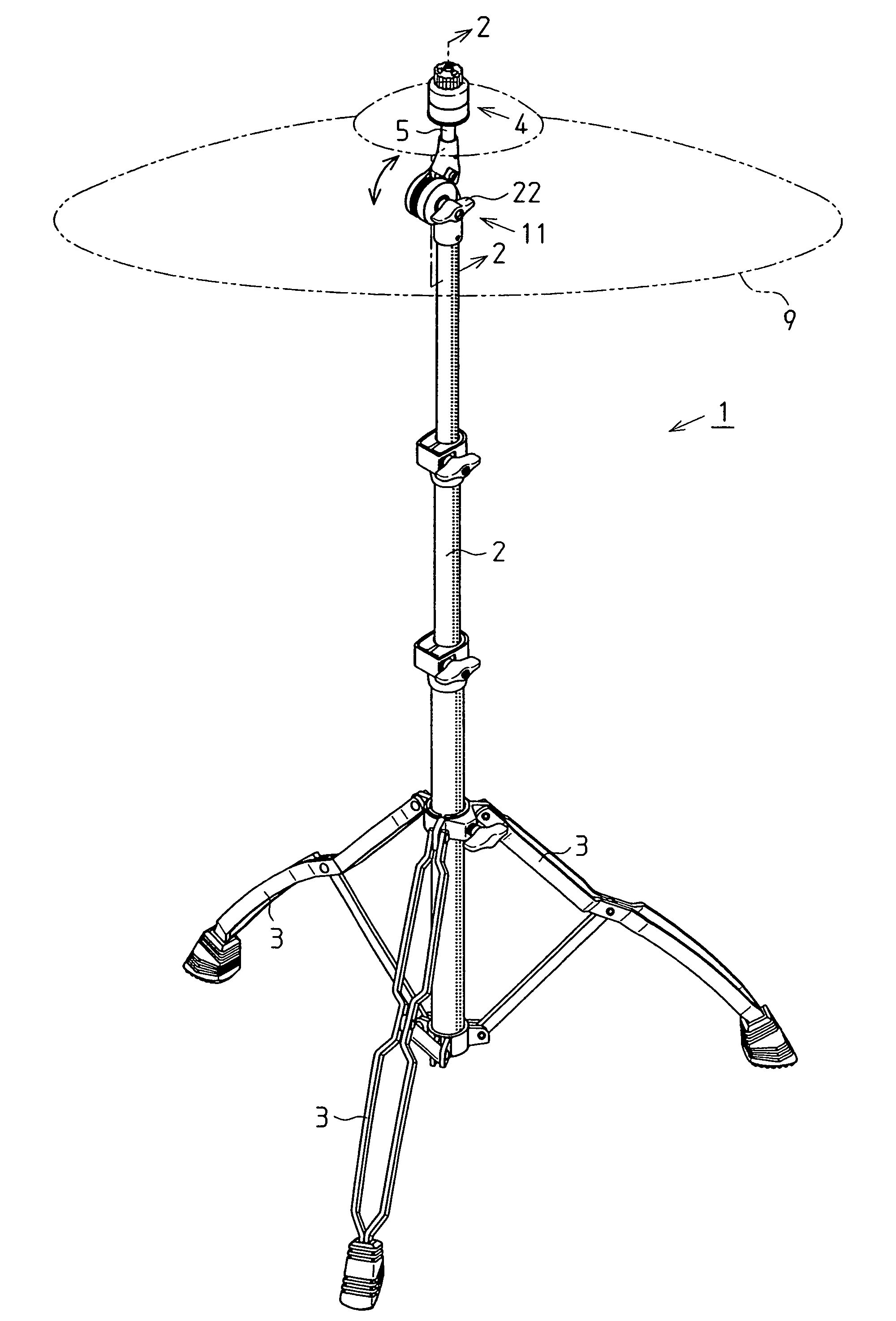
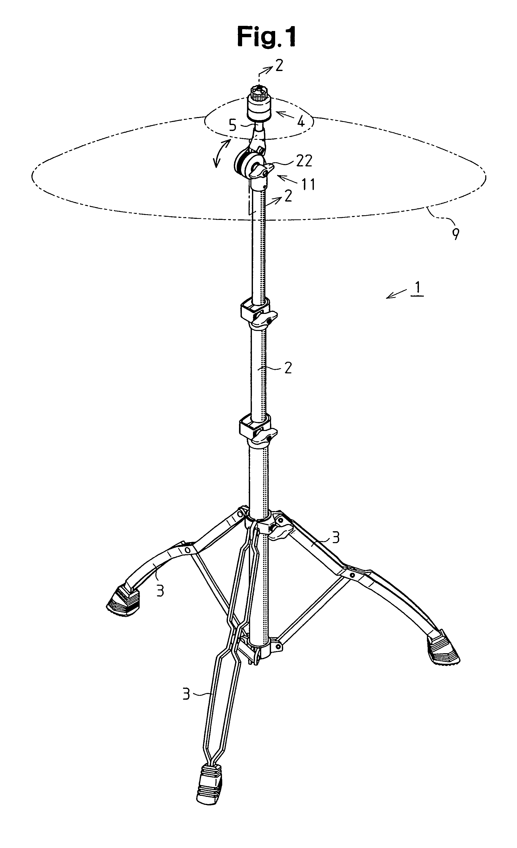
[0022]As shown in FIG. 1, a musical instrument stand 1 includes a pipe 2, which is supported by three legs 3 and extends upward, an angle adjustor 11 (hereafter, simply referred to as an “adjustor 11”), which is connected to the upper end of the pipe 2, and a musical instrument support 4, which is attached on the top of the adjustor 11. In the present embodiment, a cymbal 9 is held by the musical instrument support 4.

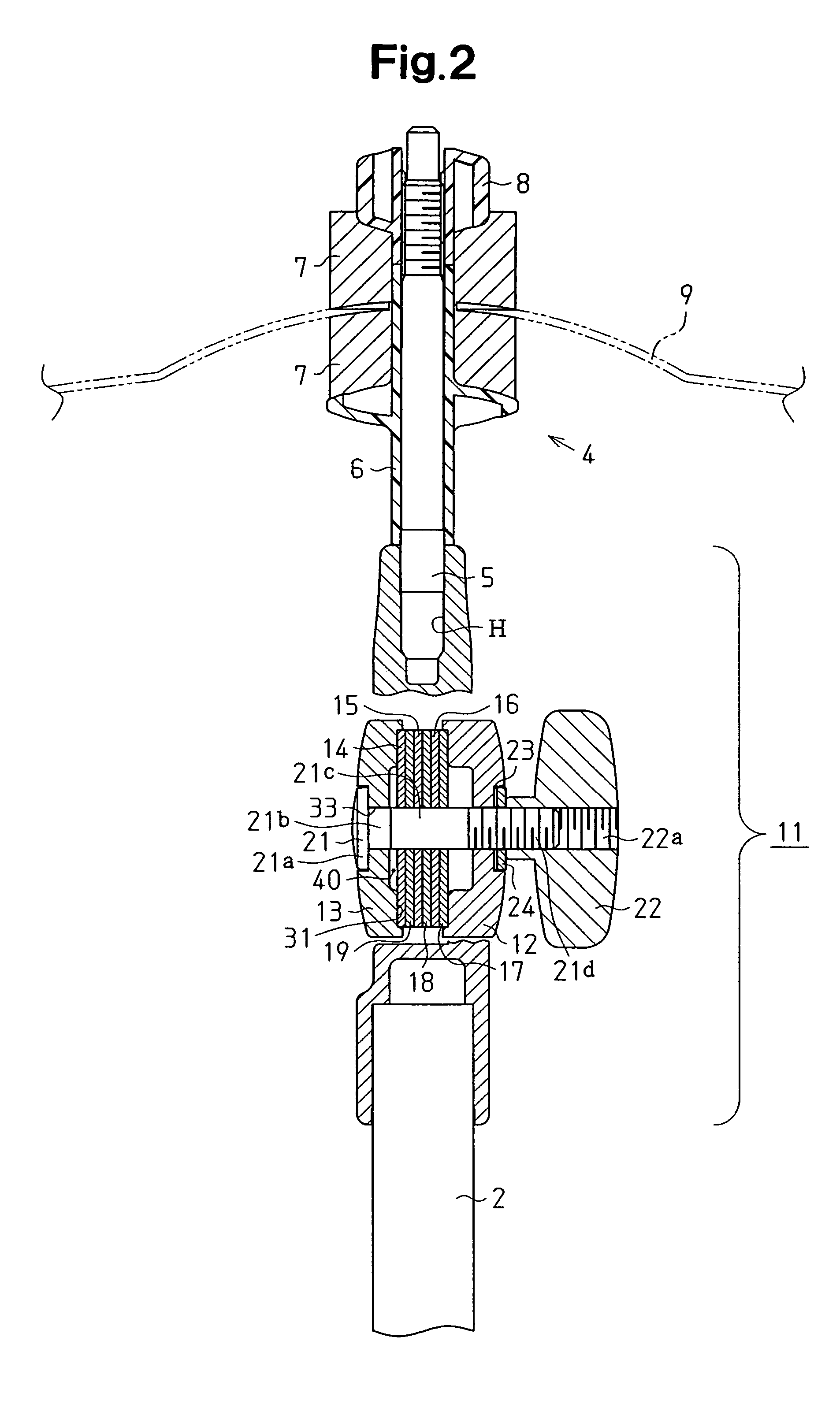
[0023]As shown in FIG. 2, the angle adjustor 11 includes a fixed member 12, a movable member 13, and a plurality of (six in the present embodiment) friction plates 14, 15, 16, 17, 18, and 19. The friction plates 14, 15, 16, 17, 18, and 19 are arranged between the fixed member 12 and the movable member 13. The angle adjustor 11 further includes a bolt 21, which extends into the movable member 13 from the outer side. The bolt 21 extends through the movable member 13, the friction plates 14 to 19, and the fixed member 12.

[0024]As shown in FIG. 3, the bolt 21 is a carriage ...

second embodiment

[0053]An angle adjustor 111 according to a second embodiment of the present invention will now be described, with reference to FIG. 7, focusing on parts differing from the first embodiment. The angle adjustor 111 of the second embodiment has the same structure as the first embodiment except in the fastening position of each screw 38, which functions as the fastener of the angle adjustor 11. The components of the angle adjustor 111 that are identical or equivalent to the components of the angle adjustor 11 are given the same reference numerals as those components and will not be described in detail.

[0054]As shown in FIG. 7, a pressing member 137 includes a plate-like head 145 and a functional piece 146 as in the first embodiment.

[0055]The pressing member 137 has a hole 148, through which the screw 38 is inserted. The hole 148 is located at a position closer to the first side wall 41a than the middle of the head 145. The hole 148 extends through the head 145 and the functional piece 1...

third embodiment

[0061]An angle adjustor 221 according to a third embodiment of the present invention will now be described with reference to FIG. 8. The second embodiment employs a pressing member 237 for the angle adjustor 221 that differs from the pressing member 137 of the angle adjustor 111 in the second embodiment. The pressing member 237 in the third embodiment does not have a part corresponding to the head 145 of the pressing member 137 in the second embodiment. Further, the pressing member 237 is formed only by a functional piece 246, which corresponds to the functional piece 146 of the pressing member 137 in the second embodiment.

[0062]Further, instead of the head 145, a plate-like cover 245 covers the top end opening 32a of the notch 32. The cover 245 is fixed to the top of the pressing member 237. Alternatively, the cover 245 may be fixed to the stepped portions 39. The cover 245 may be fixed to the pressing member 237 or stepped portions 39 by an adhesive, an adhesive tape, or a screw. ...


PUM


Abstract

An angle adjustor includes a fixed member, a movable member, a plurality of friction plates arranged between the fixed and movable members, and a bolt connecting the fixed and movable members. The fixed member and the movable member each have a notch for receiving a pressing member that presses the friction plates against the surface of the notch. Each pressing member is fixed to the fixed member or movable member in a direction substantially parallel to the axis of the bolt. The friction plates are fixed between the notch and the pressing member.

Description

BACKGROUND OF THE INVENTION[0001]The present invention relates to an angle adjustor, and more particularly, to an angle adjustor for a musical instrument.[0002]It is desirable that the angular position of a musical instrument, such as a cymbal and a snare drum supported by a floor stand, a cymbal supported on a bass drum, or a tom-tom, be adjusted in accordance with the performer's preferences, physical features, etc. Once the angular position of a musical instrument is adjusted, it is desired that the musical instrument be stably supported during performance at the adjusted angle. U.S. Pat. No. 5,146,808 describes an angle adjustor 61, as shown in FIG. 9. The angle adjustor 61 includes a movable member 63, a fixed member 62, and a plurality of friction plates 64a and 64b. The movable member 63 is connected to a musical instrument, such as a cymbal. The fixed member 62 is connected to a main body of a stand. The plurality of friction plates 64 are arranged between the movable member...

Claims


Application Information

Patent Timeline
Patent Type & Authority Patents(United States)
IPC IPC(8): G10D13/02
CPCF16M11/10F16M11/245F16M11/28F16M2200/022
Inventor SATO, NAOKIMIYAJIMA, HIDEYUKI
Owner HOSHINO GAKKI COMPANY LIMITED
Why Eureka
Try Eureka