Check patentability & draft patents in minutes with Patsnap Eureka AI!

Image forming apparatus for controlling variation of image density and toner concentration

a technology of image density and toner concentration, which is applied in the direction of electrographic process apparatus, instruments, optics, etc., can solve the problems of reducing the developability of toner, increasing the charging potential of such toners, and reducing the amount of toner to be adhered on the recording sh

Inactive Publication Date: 2008-06-17
RICOH KK
View PDF16 Cites 10 Cited by
  • Summary
  • Abstract
  • Description
  • Claims
  • Application Information

AI Technical Summary

Benefits of technology

[0017]In another case, when images of smaller image area are printed continuously with lower image density, the image forming apparatus may control the toner concentration to a preferable level with less emphasis on the image density. In this case, an image density may become unfavorably lower.

Problems solved by technology

Accordingly, a charging potential of such toners may increase, and thereby a toner amount to be adhered on the recording sheet may become smaller because of an imbalance between a latent image potential on the photoconductive member (i.e., image carrying member) and the charging potential of such toners.
Such condition may downgrade a developability of toner, so that an image density on the recording sheet may become lower.
If the toner concentration has increased beyond a specified level, unpreferable phenomenon, such as toner scattering and fogging, may occur.
However, even if the toner concentration in the developing unit is maintained within a predetermined range, a change of developer condition may downgrade a developability of the developer.
In this case, the toner concentration may unfavorably exceed the range set for the toner concentration.
In this case, an image density may become unfavorably lower.
A change of the charge voltage Vc may cause a change of adhering capability of toner to the photoconductive member 1, a change of transfer-ability of toner image, and unfavorable image development on the photoconductive member 1 by an excessive transfer bias voltage.
Such a drawback may occur depending on conditions and a type of developer to be used in the image forming apparatus 100.

Method used


Image

  • Image forming apparatus for controlling variation of image density and toner concentration
  • Image forming apparatus for controlling variation of image density and toner concentration
  • Image forming apparatus for controlling variation of image density and toner concentration

Examples


Embodiment Construction

[0086]In describing example embodiments shown in the drawings, specific terminology is employed for the sake of clarity. However, the disclosure of this present invention is not intended to be limited to the specific terminology so selected and it is to be understood that each specific element includes all technical equivalents that operate in a similar manner.

[0087]Referring now to the drawings, wherein like reference numerals designate identical or corresponding parts throughout the several views, an image forming apparatus according to an example embodiment is described with a particular reference to FIGS. 5 to 12.

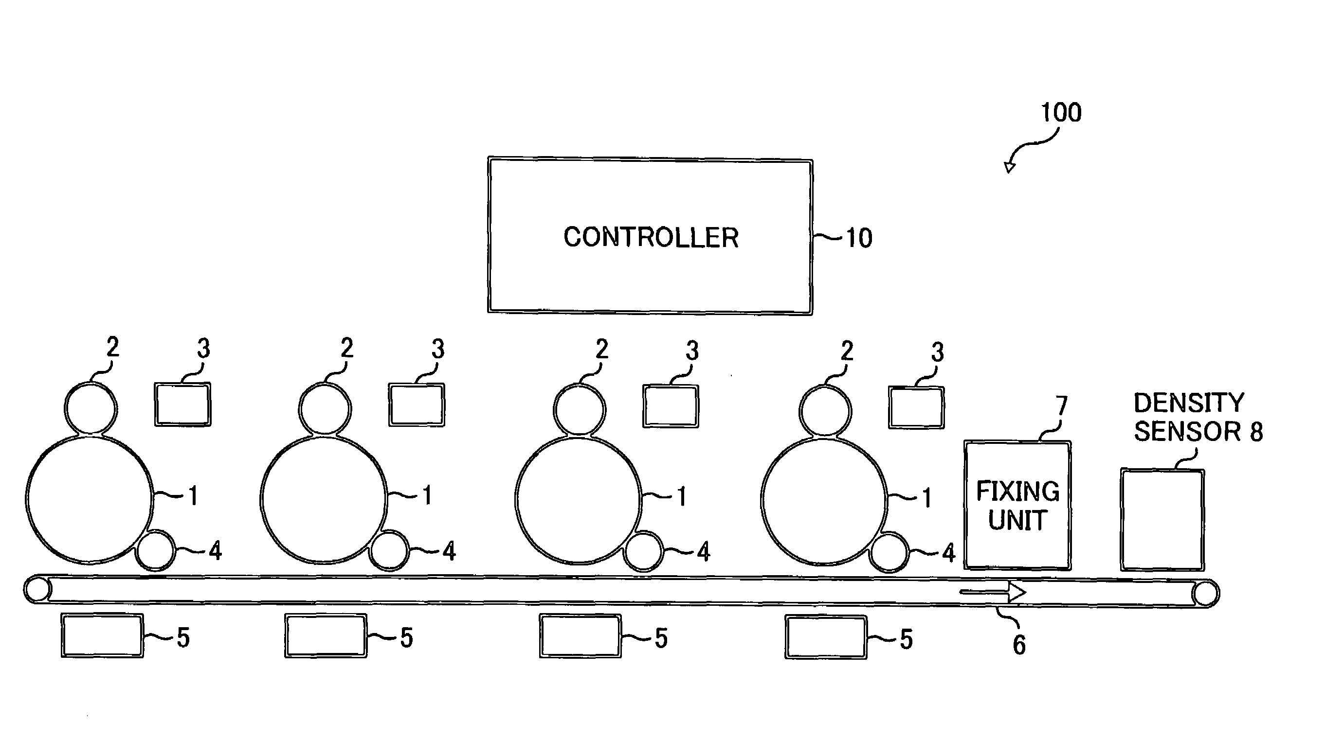
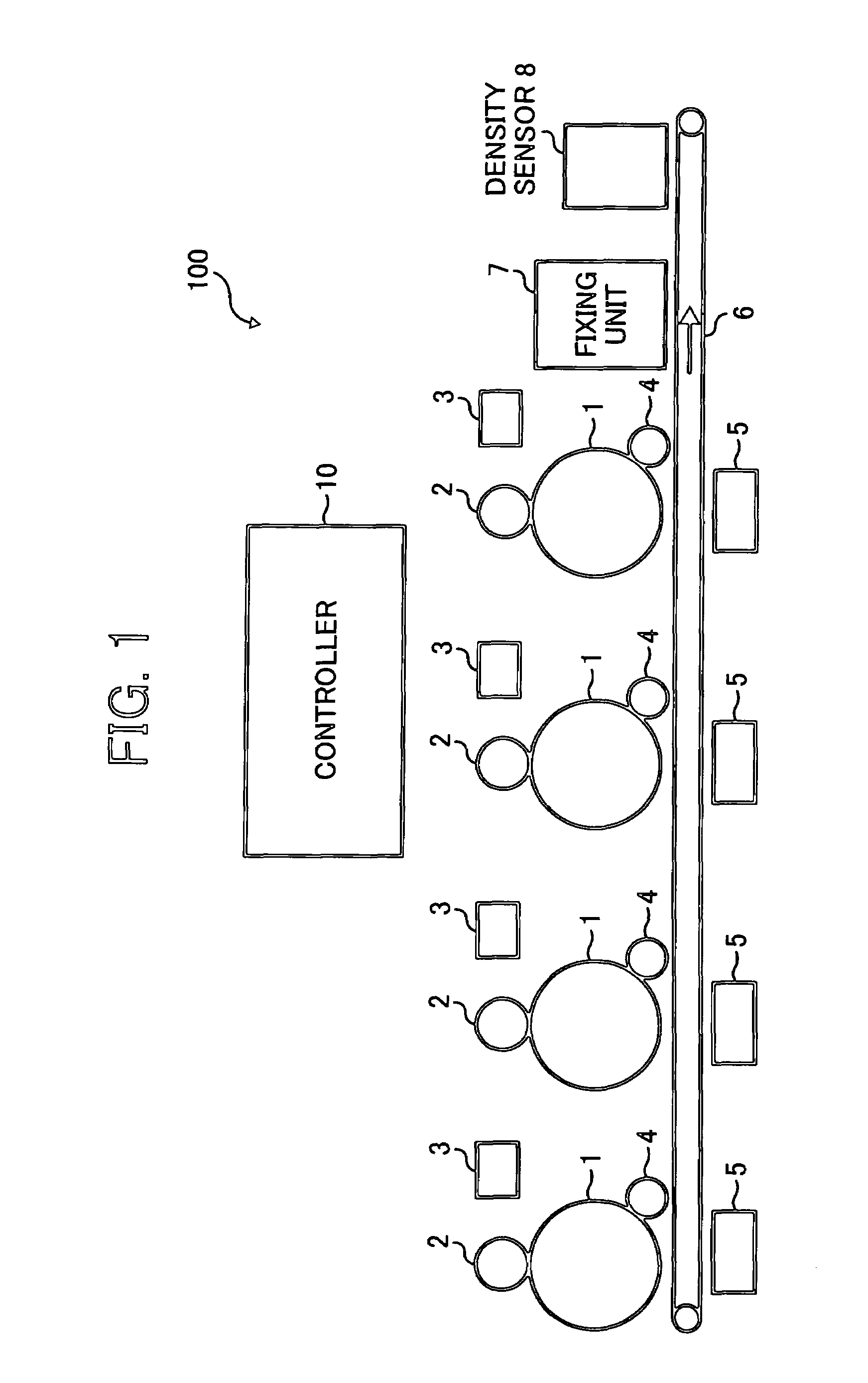
[0088]FIG. 5 is a schematic configuration of an image forming apparatus 110 according to an example embodiment, which includes a plurality of developing units having a two-component developer. FIG. 6 is a schematic expanded view of a developing unit and a photoconductive member in the image forming apparatus 110 shown in FIG. 5.

[0089]As shown in FIG. 5, the image formin...


PUM


Abstract

An image forming apparatus includes an image carrying member, a developing unit, an image density detector, a toner concentration detector, a toner concentration controller, and an output adjustment unit. The image carrying member forms a reference latent image pattern. The developing unit develops the reference latent image pattern as a reference image pattern with a two-component developer. The image density detector detects an image density of the reference image pattern. The toner concentration detector detects a toner concentration in the two-component developer. The toner concentration controller controls the toner concentration based on the image density detected by the image density detector. The output adjustment unit adjusts a toner concentration sensing level of the toner concentration detector with a sensor control voltage. The toner concentration is controlled by a target voltage with reference to the image density. The toner concentration range is changed by changing the sensor control voltage.

Description

CROSS-REFERENCE TO RELATED APPLICATIONS[0001]This application claims priority from Japanese patent application No. 2005-125793, filed Apr. 22, 2005, the entire contents of which are incorporated herein by reference.BACKGROUND OF THE INVENTION[0002]1. Field of the Invention[0003]The present disclosure generally relates to an image forming apparatus having an image density detector and a toner concentration detector, and more particularly to an image forming apparatus which adjusts a image density and toner concentration with an image density detector and toner concentration detector.[0004]2. Discussion of the Background[0005]An image forming apparatus includes a photoconductive member, a charger to charge the photoconductive member, an optical writing unit to write a latent image on the charged photoconductive member, a developing unit to develop the latent image formed on the photoconductive member as a toner image with an effect of developing bias voltage, and a transfer unit to tr...

Claims


Application Information

Patent Timeline
Patent Type & Authority Patents(United States)
IPC IPC(8): G03G15/08
CPCG03G15/0853G03G15/5058G03G15/0849G03G15/0194G03G2215/00059G03G2215/0607
Inventor ISHIBASHI, MIKIO
Owner RICOH KK
Features
  • R&D
  • Intellectual Property
  • Life Sciences
  • Materials
  • Tech Scout
  • Unparalleled Data Quality
  • Higher Quality Content
  • 60% Fewer Hallucinations
Learn More