Nasal inserts

a technology of nasal inserts and nasal passages, which is applied in the field of nasal inserts, can solve the problems of reducing sleep, reducing airway size, and deteriorating intimacy and relationships, and achieves the effects of improving nasal breathing, reducing snoring, and increasing airflow through the nasal passages

Inactive Publication Date: 2008-06-24
SANOSTEC CORP
View PDF41 Cites 42 Cited by
  • Summary
  • Abstract
  • Description
  • Claims
  • Application Information

AI Technical Summary

Benefits of technology

[0011]The object of the present invention is to reduce snoring by increasing the airflow through the nasal passages. It is a further object to provide devices that improve nasal breathing by increasing airflow through the nasal passages during sleep. It is another object of the present invention to treat chronic sinusitis.
[0017]In some forms of both the single tube or dual tube embodiments of the invention, the tubular elements have a tab extending from the first (i.e. relatively large) end which extends substantially parallel to the tube axis and is elongated in the direction of the tube axis. In yet another embodiment, each tube element has a tab support extending radially from the first end in a direction substantially perpendicular to the tube axis. At least one tab extends from the tab support, and is elongated in the direction of the tube axis. The tabs may be resiliently deformable, so as to permit elastic deformation in use, providing a frictional holding force when engaging the nose. Alternatively, the tabs may be non-resiliently deformable, permitting inelastic deformation, so that a user can “pinch” the tabs so that they capture and hold the nose. The non-resilient tabs are preferably made of metal, for example, copper, aluminum, but may be made of other materials that may be non-resiliently deformed. The tab preferably includes at least one relatively small protrusion extending from a distal end of the tab. The distal end is distal from the first end of the tubular element. The relatively small protrusion may also extend from the outer surface of the tubular element opposing the distal end of the tab. The tab and the protrusion help to prevent the device from slipping out of a user's nose.
[0018]The tubular element includes, preferably at its large end, an open-faced channel extending about its tube axis. The device further includes a filter having a peripheral frame contoured to snap-fit in the open-faced channel. The filter includes a filter medium, preferably a paper filter or metal or plastic mesh coated with absorbent materials, spanning the peripheral frame. In an alternate embodiment, at least one relative small protrusion extends from an inner surface of the channel. The filter is adapted to snap-fit over the protrusion into the channel and is retained by the protrusion, so that the filter cannot slip out from the channel when the device is in use. In a preferred embodiment, the protrusion extends throughout an inner circumference of the channel.

Problems solved by technology

Anatomical deformities in the airway such as large tonsils and adenoids, excessive length of the soft palate, or broken or crooked nose, can also diminish the airway size.
Snoring can causes relationship problems between partners, leading to a loss of intimacy and deterioration of relationships.
Decreased sleep, or insufficient restful sleep increases irritability, poor memory and concentration and decreased work performance.
However, the success rate is only 50%.
These dental devices can be expensive custom-fit, or inexpensive over the counter mouth pieces.
While these strips may dilate the nasal passages to small degree, they do not work well in patients with anatomical deformities or obstructions in the nose.
These devices can be cumbersome, unsightly, painful, or expensive, and the patient may abandon these approaches in short time.
Chronic sinusitis is difficult to treat because it responds slowly to medications.
These treatments generally cannot get directly to the source of the problem, or may cause side effect, for example, frequently using nasal spray may worsen the symptom.

Method used


Image

  • Nasal inserts
  • Nasal inserts
  • Nasal inserts

Examples


Embodiment Construction

[0037]The nasal breathing assist devices according to the various aspects of the invention are shown in FIGS. 1 through 10. These devices overcome the deficiencies in the currently available devices. The illustrated devices are small, inconspicuous in use, and require no special attachments or fittings. The devices are worn inside the nose, so that the nasal passages are kept open from the inside, rather than by external means. This allows the devices to maintain airways in noses where anatomical abnormalities diminish the effectiveness of externally applied strips. The devices can be used alone, or in conjunction with other snore-reducing aids, such as pillows and medicated nasal sprays.

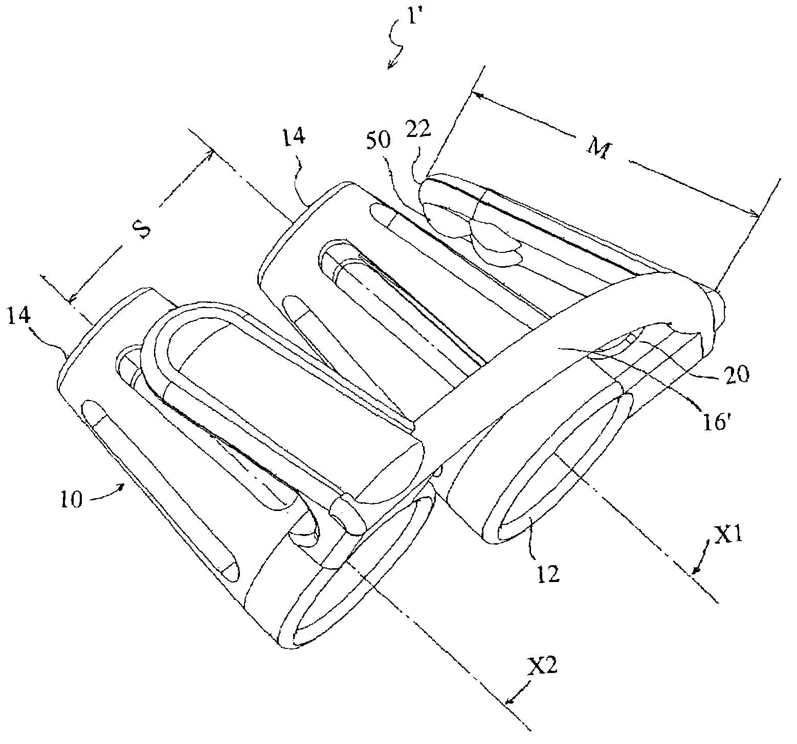
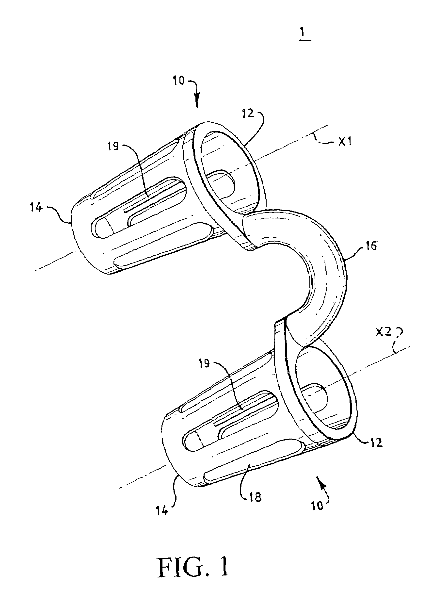
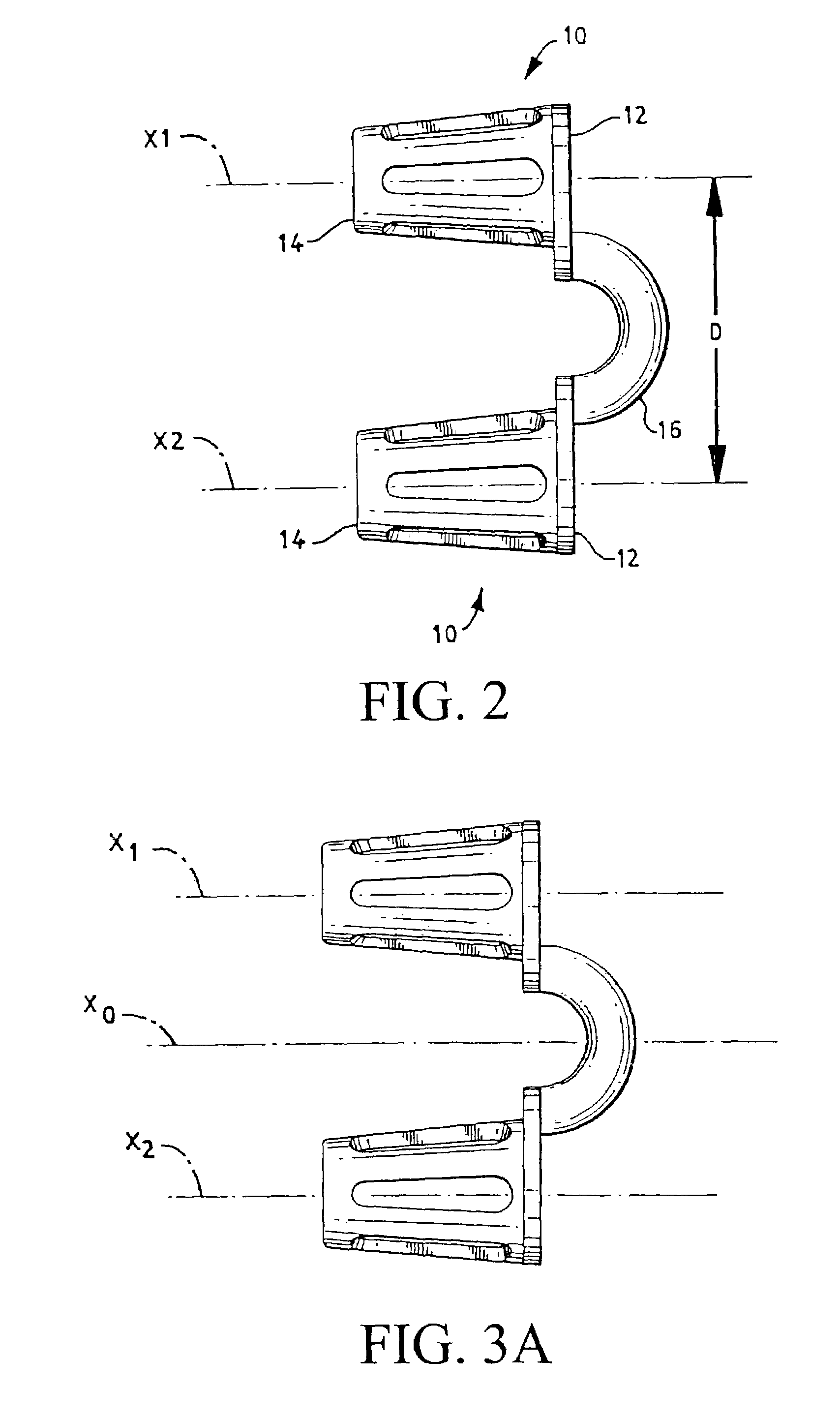
[0038]In the embodiment shown in FIG. 1, the nasal breathing assist device 1 comprises generally a pair of open ended tubular elements 10 connected together by a coupler element 16.

[0039]The tubular elements 10 are generally circular in cross section and extend a distance along tube axes X1 and X2 f...


PUM


Abstract

A nasal breathing assist device includes a pair of open-ended tubular elements each extending along a central tube axis between a relatively large first end and a relatively small second end, a coupler element extending between the first ends of the tubular elements, and at least one non-resilient tab extends from the first end toward the second end of the tubular element. The tab includes at least one relatively small protrusion extending from a distal end of the tab toward the tubular element. The device may further includes a filer having a peripheral frame contoured to be snap-fitted in an open-faced channel defined within the tubular element. The device may further includes a removable medication carrier which is adapted to bear a therapeutic agent and adapted to insert into the open-faced channel of the tubular element. The tubular element may define at least one channels on an inner surface of the tubular element to receive edges of the medication carrier.

Description

CROSS-REFERENCE TO RELATED APPLICATIONS[0001]This application is a continuation in part of U.S. patent application Ser. No. 09 / 862,966, filed on May 22, 2001 now U.S. Pat. No. 6,562,057, the disclosure of which is incorporated herein by reference.FIELD OF THE INVENTION[0002]This invention pertains to methods and devices for nasal breathing assist devices, in particular to methods and devices for improving nasal breathing and reducing snoring.BACKGROUND OF THE INVENTION[0003]Snoring is a condition characterized by rough, loud, rattling breathing or inspiratory noise during sleep or deep coma. The characteristic snoring noise is produced by vibration of the soft palate (the soft tissue in the roof of the mouth near the throat) or vocal chords by inhaled or exhaled air. As the soft palate vibrates, the lips, cheeks, and nostrils may also vibrate, making the snoring louder.[0004]Snoring can be caused by underlying physical or disease conditions that restrict air passages and force the p...

Claims


Application Information

Patent Timeline
Patent Type & Authority Patents(United States)
IPC IPC(8): A61M29/00A61FA61F5/08
CPCA61F5/08
Inventor SANTIN, ERNESTMACDONALD, LOUISE
Owner SANOSTEC CORP
Why Eureka
Try Eureka