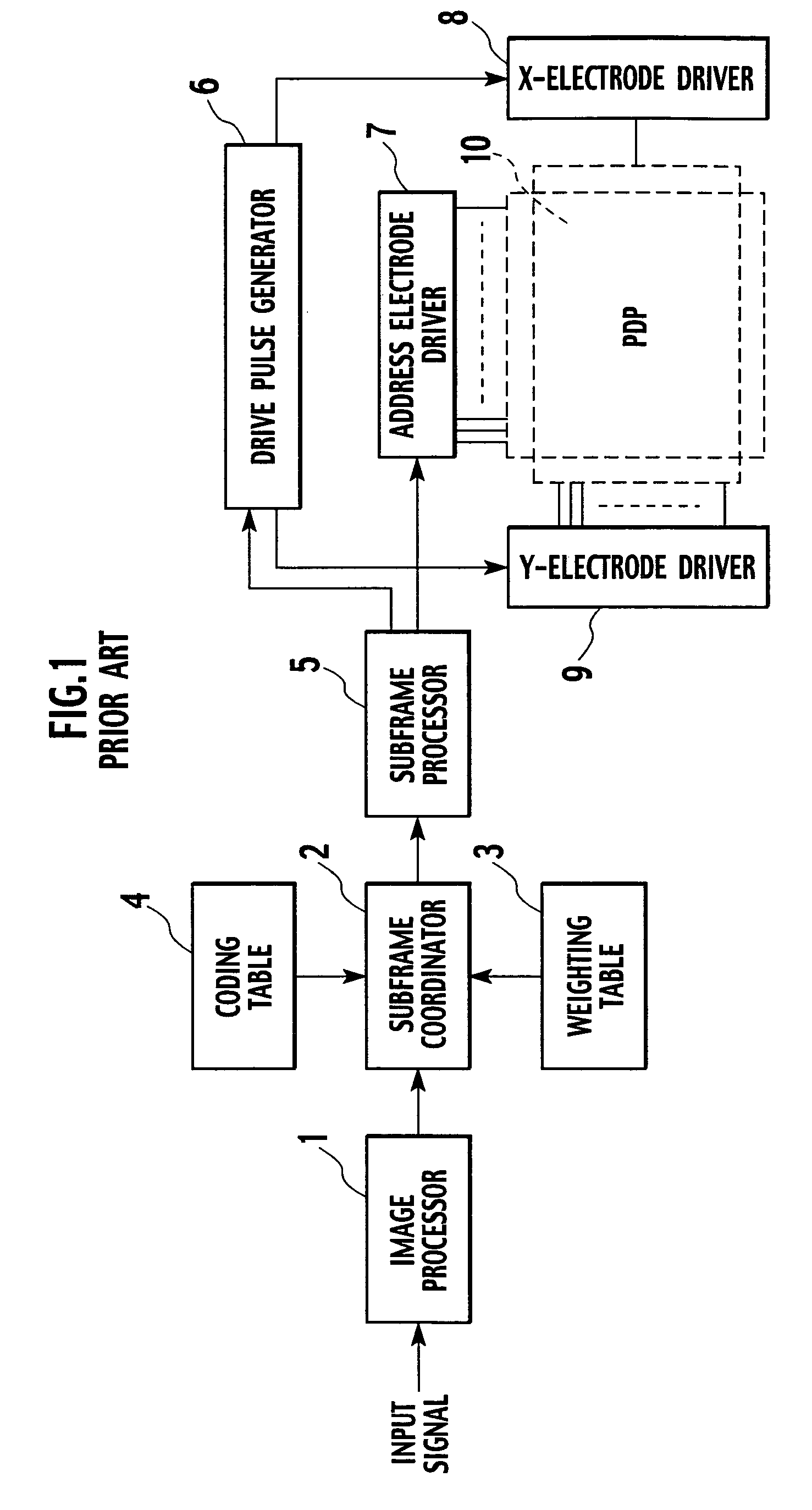
Display apparatus

a technology of display apparatus and display screen, which is applied in the direction of identification means, instruments, computing, etc., can solve the problems of false contours and image quality degradation

Active Publication Date: 2008-06-24
RAKUTEN GRP INC
View PDF18 Cites 8 Cited by
  • Summary
  • Abstract
  • Description
  • Claims
  • Application Information

AI Technical Summary

Benefits of technology

[0018]An object of the present invention is to provide a display apparatus capable of solving the problem of false contours when displaying dynamic or still images.
[0020]According to the first aspect, the subframe coding tables having different gray-scale-level input / output characteristics are cyclically and alternately employed at intervals of every frame, or every pixel, or every frame and every pixel of an input image signal. As a result, a location where a gray-scale level increases to cause false contours is moved to another location in the next frame, or such a location is temporally distributed to surrounding pixels. Then, the location to cause false contours never moves with a line of sight of a person who watches images displayed on the display apparatus. In this way, the first aspect minimizes false contours and properly displays dynamic images.
[0022]According to the second aspect, a display gray-scale level of k involves a first number of subframes to be selected, a display gray-scale level of k+1 involves a second number of subframes to be selected that is equal to or greater than the first number by one, and a display gray-scale level of k+2 involves a third number of subframes to be selected that is equal to or greater than the second number by one. In this way, the second aspect nonlinearly increases the number of subframes to be selected according to an increase in gray-scale level. This configuration minimizes gray-scale steps displayed on a display apparatus such as a PDP that determines a display gray-scale level according to not only sustain pulses generated during sustain discharge periods but also pixel selecting pulses generated during addressing periods.
[0024]According to the third aspect, the at least two sets of subframe coding tables generated by the table generator and alternately used at intervals of every frame, or every pixel, or every frame and every pixel of an input image signal are configured such that a location in a first set of the at least two sets of subframe coding tables where a first of two adjacent output gray-scale levels involves an “n−1”th subframe as a top subframe among subframes selected for the first output gray-scale level and a second thereof involves an “n”th subframe as a top subframe among subframes selected for the second output gray-scale level differs from that in a second set of the at least two sets of subframe coding tables. The location in the first set of subframe coding tables where a first output gray-scale level involves the “n−1”th subframe as a top subframe and a second output gray-scale level involves the “n”th subframe as a top subframe frequently causes false contours due to a gray-scale-level step-up. The third aspect moves this location to another in the next frame and distributes the location of false contours to surrounding pixels, to thereby prevent the location of false contours from moving with a line of sight of a viewer. In this way, the third aspect minimizes false contours and properly displays dynamic images.

Problems solved by technology

The phenomenon is specific to the display apparatus employing the in-frame time division displaying method and deteriorates image quality.
This related art, however, involves some gray-scale levels each selecting the same subframes in both the light emission patterns A and B to unavoidably cause false contours.

Method used


Image

  • Display apparatus
  • Display apparatus
  • Display apparatus

Examples


first embodiment

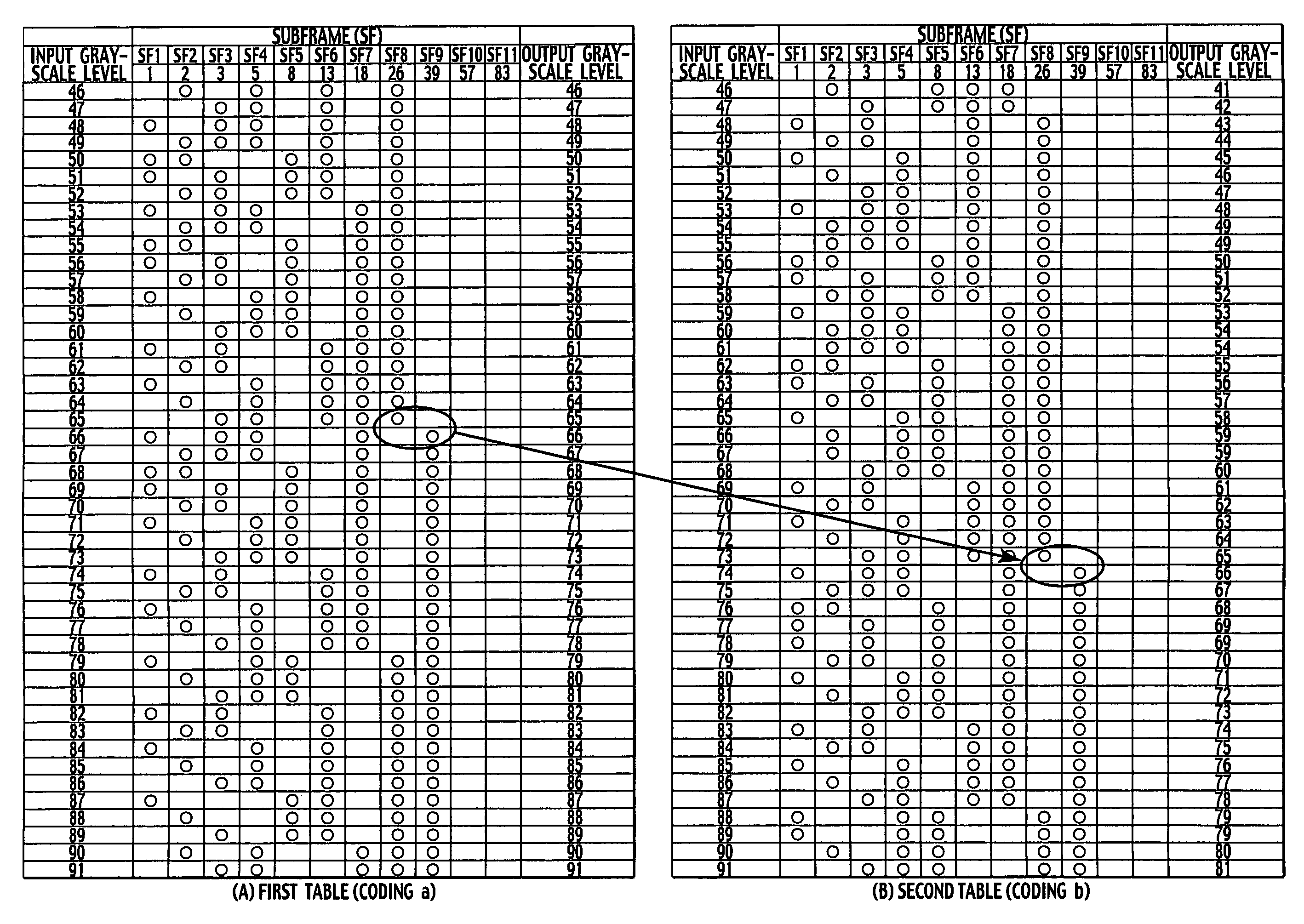
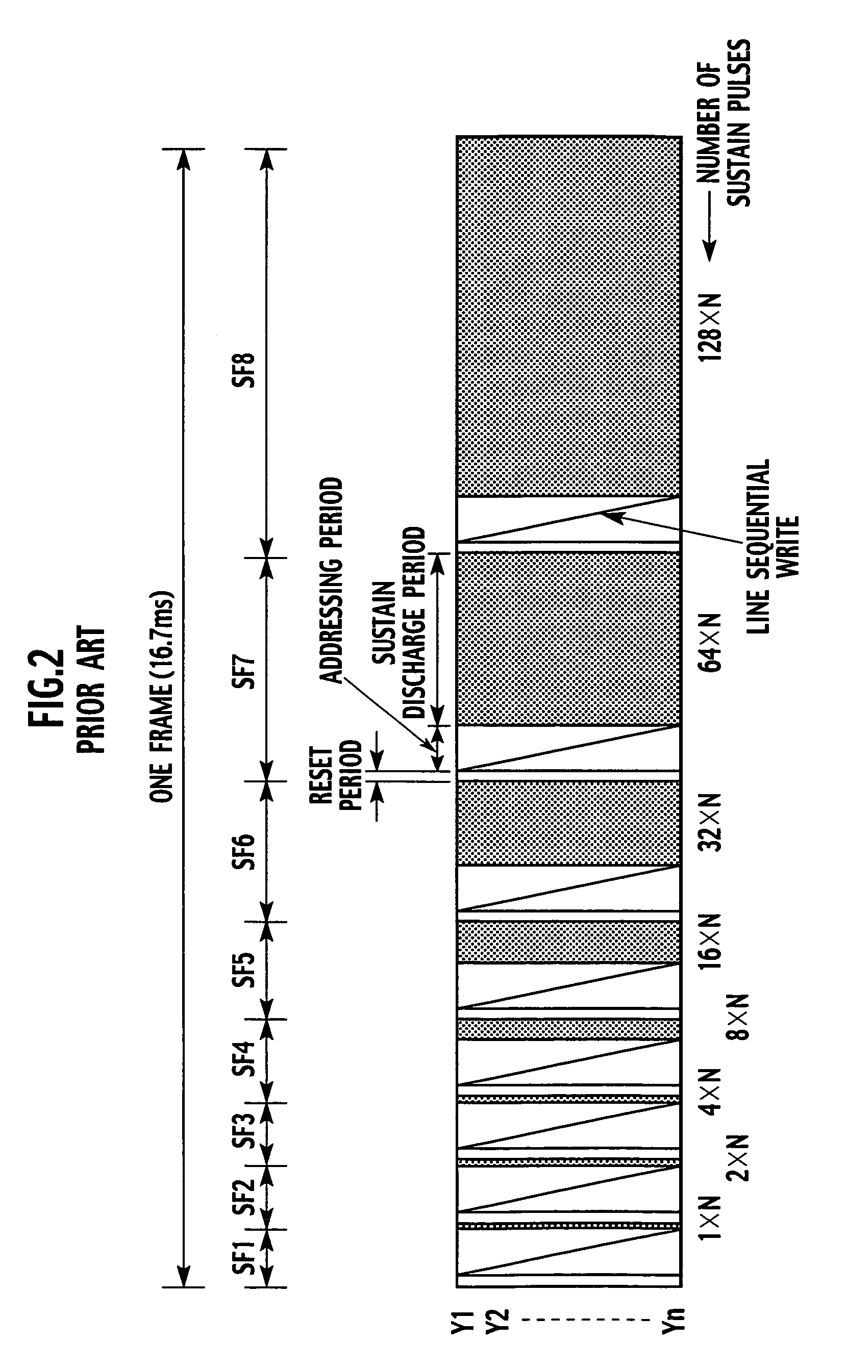
[0057]To solve the problem of false contours, the first embodiment of the present invention alternates the number of gray-scale levels from frame to frame. FIG. 5 shows a subframe structure according to the first embodiment. In FIG. 5, the first embodiment employs eleven subframes SF1 to SF11 each including a reset period, an addressing period, and a sustain discharge period. The sustain discharge periods are depicted with patterns. The reset periods of the subframes SF1 to SF11 are equal to one another, and the addressing periods thereof are also equal to one another. The sustain discharge periods of the subframes SF1 to SF11 differ from one to another.

[0058]The brightness of an image to be displayed is determined by the number of sustain pulses generated during a sustain discharge period, i.e., the weights of the subframes. In FIG. 5, the subframes SF1 to SF11 are allocated with weights 1, 2, 3, 5, 8, 13, 18, 26, 39, 57, and 83, respectively. The subframes SF1 to SF6 are weighted ...

second embodiment

[0081]The second embodiment of the present invention will be explained with reference to the accompanying drawings. FIG. 15 shows pixel arrangements on a display panel that change from one to another at intervals of one frame according to the second embodiment. In FIG. 15, pixels are divided into groups A and B, and the group-A pixels and group-B pixels are arranged in a hound's-tooth check. Namely, a group-A pixel is surrounded by group-B pixels, and a group-B pixel is surrounded by group-A pixels.

[0082]Any pixel that is in the group A in a first frame is changed to the group B in a second frame, and any pixel that is in the group B in the first frame is changed to the group A in the second frame. In this way, the pixel arrangements are alternated frame by frame. FIG. 16 shows temporal changes of the pixel arrangements. The pixels in the group A alternate the coding a of 256 gray-scale levels and the coding b of 230 gray-scale levels frame by frame, and at the same time, the pixels...

third embodiment

[0100]FIG. 19 is a graph showing an example of a technique of changing the gray-scale level of an input signal according to the third and fourth embodiments of the present invention. In FIG. 19, an abscissa represents the gray-scale level of an input signal, and an ordinate represents the gray-scale level of an output signal. When an input signal has a gray-scale level of 256, coding “a” provides an output signal having a gray-scale level of 256. At this time, coding “b” provides an output signal having a gray-scale level of 230 which is lower than that provided by the coding a. Each of the coding a and b has a linear gray-scale-level input / output characteristic.

[0101]The dual coding according to the present invention will briefly be explained with reference to FIG. 20. FIG. 20(A) shows a basic subframe coding table that weights a subframe by the “n”th power of 2. The table involves subframes SF1 to SF5 that are weighted by 1, 2, 4, 8, and 16, respectively. In the table of FIG. 20(A...


PUM


Abstract

A display apparatus divides each frame period of an input image signal into a plurality of subframes and selects the subframes according to a gray-scale level of the input signal, to display a gray-scale image. The display apparatus alternately employs two sets of tables having different gray-scale-level input / output characteristics, to move locations to cause false contours frame by frame, thereby minimizing false contours.

Description

BACKGROUND OF THE INVENTION[0001]1. Field of the Invention[0002]The present invention relates to a display apparatus, and particularly, to a display apparatus such as a plasma display panel (hereinafter referred to as PDP) that divides a frame period of an image signal into a plurality of subframes and selectively activates the subframes to display gray-scale images.[0003]2. Description of Related Art[0004]The PDP drives each pixel in a binary mode or an ON / OFF mode. To display gray-scale images, the PDP divides a frame period (16.7 ms) of an image signal into subframes having different light emitting periods, respectively. The subframes are selectively driven according to a gray-scale level to display, so that a human eye may observe a gray-scale image due to a visual integration effect. The display apparatus employing the in-frame time division displaying method is disclosed in, for example, Japanese Unexamined Patent Application Publication No. Hei-7-271325.[0005]FIG. 1 is a bloc...

Claims


Application Information

Patent Timeline
Patent Type & Authority Patents(United States)
IPC IPC(8): G09G3/28G09G5/10G09F9/313G09G3/20H01J17/49
CPCG09G3/2022G09G3/2803G09G2320/0261G09G2320/0266G09G2320/0271G09G2320/0285
Inventor OHSHIMA, YOSHINORI
Owner RAKUTEN GRP INC
Why Eureka
Try Eureka