Knee bolster structure

a bolster structure and knee technology, applied in the direction of vehicular safety arrangements, pedestrian/occupant safety arrangements, vehicle components, etc., can solve the problems of requiring a lot of development time and cost, and the inability to exhibit impact-absorbing performance, so as to increase the strength of the upper impact-absorbing section and reduce the lower impact-receiving portion

Inactive Publication Date: 2008-07-01
CALSONIC KANSEI CORP
View PDF6 Cites 37 Cited by
  • Summary
  • Abstract
  • Description
  • Claims
  • Application Information

AI Technical Summary

Benefits of technology

[0011]According to the present invention, the impact-absorbing section and the knee-receiving member movement section are structurally divided or separated to afford different functions thereto, respectively and can be combined together, so that when plural kinds of impact-receiving sections and knee-receiving member movement section are preliminarily prepared, appropriate combinations can be selected among them to cope with many types of cars. With respect to plural cars which have similar shapes and qualities around instrument panels, a common section can be used for either one of the impact-absorbing section and the knee-receiving member movement section, while simply modified parts having slightly changed dimensions, etc. are prepared and used for the other. Thus, the costs and developing time period can be reduced by the measure that the impact-absorbing section and the knee-receiving member movement section are structurally divided from each other as separate sections and combined together.
[0034](2) The impact-mitigating means is a decelerating portion provided at an open-side end of the elongate hole to reduce the speed of the operating shaft.

Problems solved by technology

It is the present situation that such knee bolster structures have been developed, designed and attached independently for respective kinds of automobiles, which have required much developing time and costs.
However, even if the knee-receiving member movement section is provided, a given impact-absorbing performance cannot be exhibited if the function of moving the knee-receiving member is collapsed with the input load before the impact-absorbing function.

Method used


Image

  • Knee bolster structure
  • Knee bolster structure
  • Knee bolster structure

Examples


Embodiment Construction

[0051]In the following, preferred embodiments of the present invention will be explained with reference to the attached drawings.

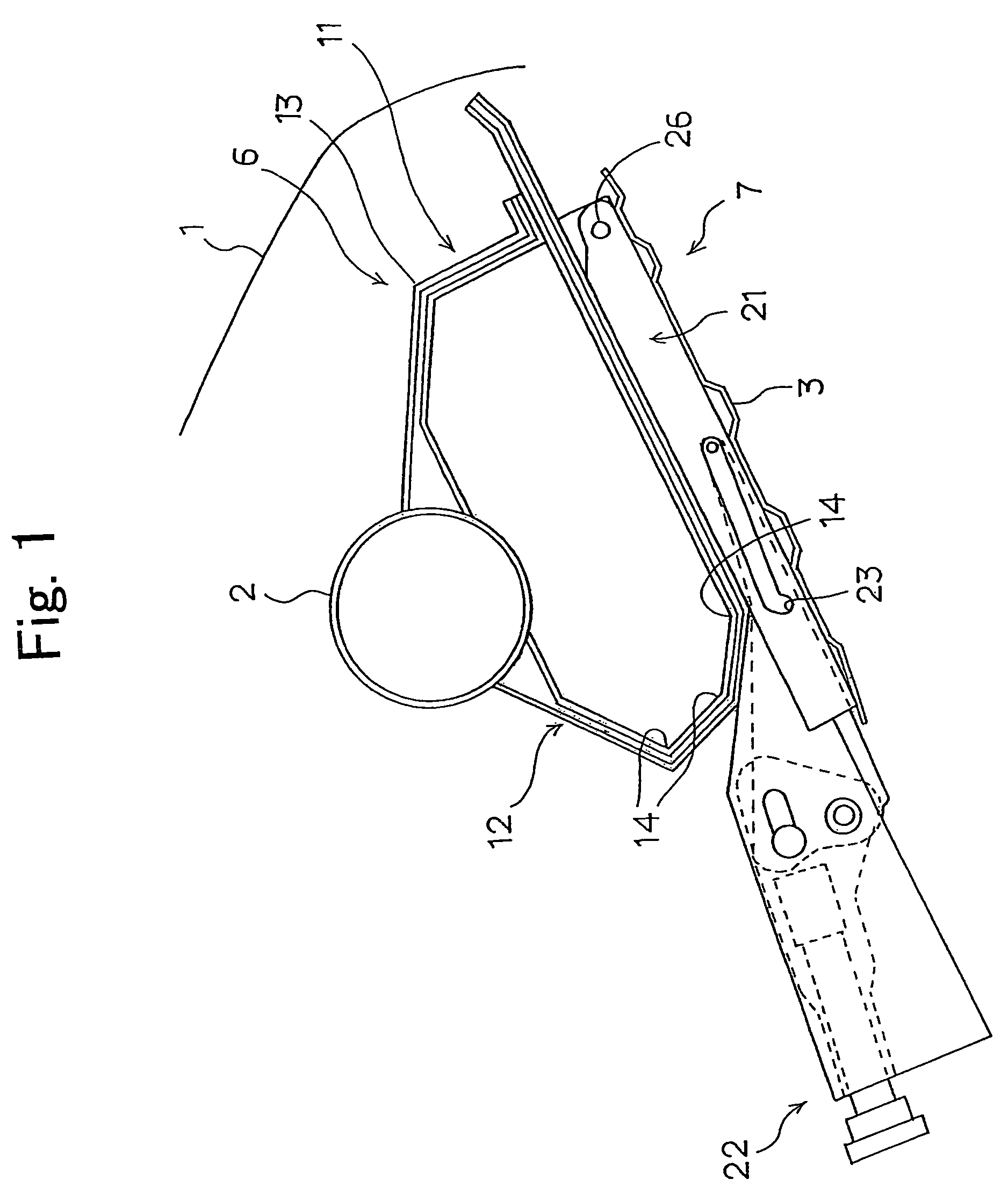
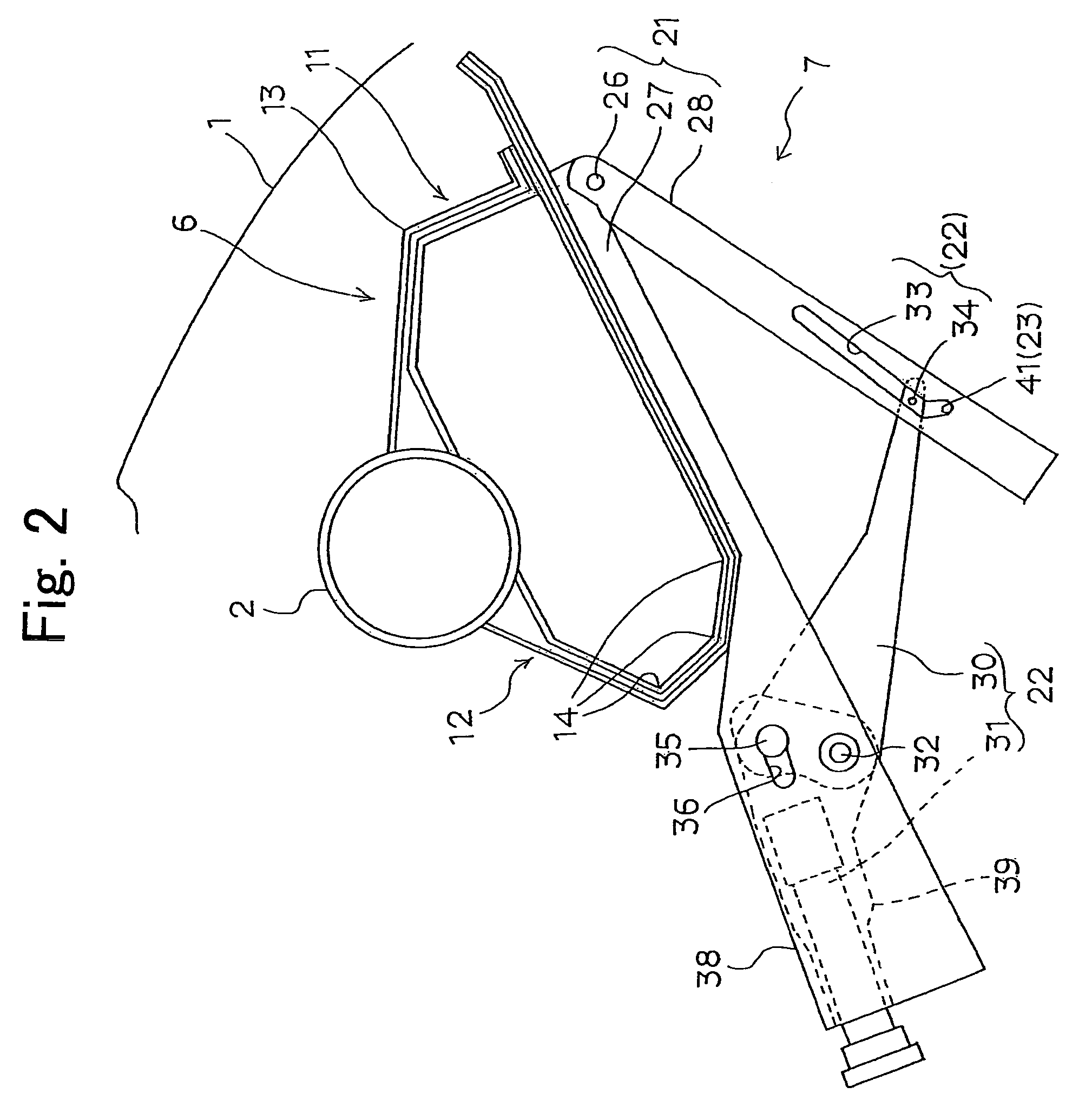
[0052]FIGS. 1 to 6 illustrate a preferred embodiment of the present invention.

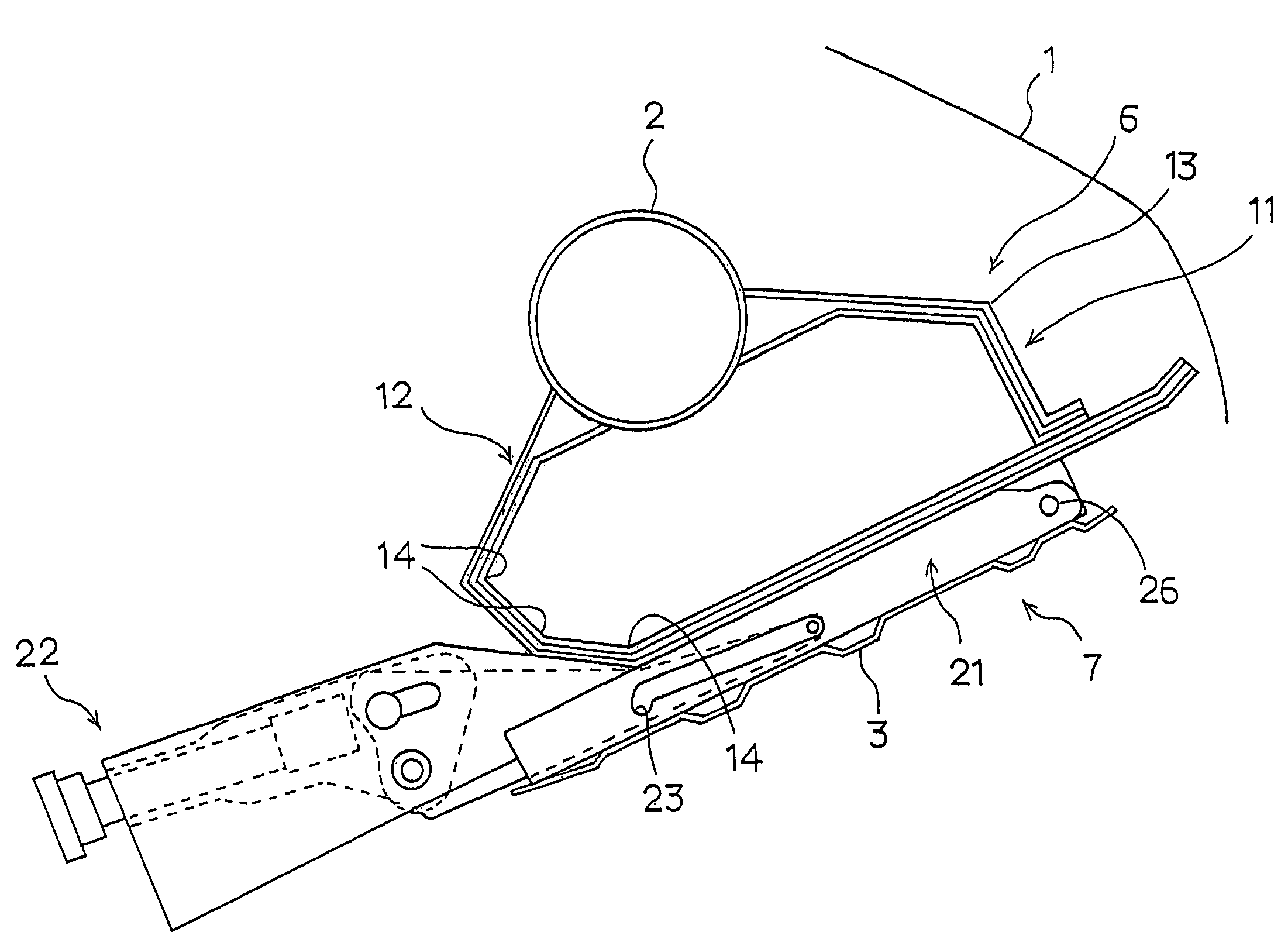
[0053]Referring to FIG. 1, an instrument panel 1 is provided at a front portion of an interior of a vehicle such as an automobile. A vehicle body-side member 2 such as a steering support member is provided inside the interior of the instrument panel 1. The vehicle body-side member 2 is a reinforcing member, which extends substantially horizontally in a width direction of the vehicle and is connected between right and left side frames of the vehicle body. A steering column not shown is attached to a driver seat side of the vehicle body-side member 2.

[0054]As shown in FIGS. 1 and 2, a knee-receiving member 3, which receives input energy from knees of a driver or front-seat passenger, is attached to the vehicle body-side member 2 as described later. The knee-receiving member 3 is ar...


PUM


Abstract

A knee bolster structure includes a vehicle-side member, a knee-receiving member, an impact-absorbing section for absorbing an input energy from knees of a driver or front-seat passenger when the knees hit the knee-receiving section, and a knee-receiving member movement section for moving the knee-receiving member to a knee-receiving position for the driver or front-seat passenger, said knee-receiving member being attached to the vehicle-side member via the impact-absorbing section and the knee-receiving member movement section, the impact-absorbing section being structurally separated from the knee-receiving member movement section.

Description

BACKGROUND OF THE INVENTION[0001](1) Field of the Invention[0002]The present invention relates to knee bolster structures to be attached to vehicles such as automobiles.[0003](2) Related Art Statement[0004]Investigations have been made to install knee bolster structures (which may be also called “knee protectors”) in interiors of vehicles such as automobiles so as to protect knees of drivers and passengers at front seats upon applications of loads, and their development has been carried out (See JP-A 6-32195 and JP-A 8-282413, for example).[0005]It is the present situation that such knee bolster structures have been developed, designed and attached independently for respective kinds of automobiles, which have required much developing time and costs.[0006]The knee bolster structure needs to be certainly operated or its operation certainty needs to be enhanced to as high a level as possible.[0007]From this point of view, a knee-receiving member of the knee bolster structure projects a...

Claims


Application Information

Patent Timeline
Patent Type & Authority Patents(United States)
IPC IPC(8): B60R21/02B60R21/00B60R21/045
CPCB60R21/045B60R2021/0051
Inventor FUNAKURA, KAZUKINAGATA, NOBUHIROKAWASHIMA, TSUTOMU
Owner CALSONIC KANSEI CORP
Why Eureka
Try Eureka