Minimum bandwidth guarantee for cross-point buffer switch

a buffer switch and minimum bandwidth technology, applied in the field of minimum bandwidth guarantee for cross-point buffer switch, can solve the problems of insufficient slack in the network, increasing the probability of data packet starvation, etc., and achieve the effect of reducing the starvation of relatively low or lower priority data packets and low delay

Inactive Publication Date: 2008-07-01
CISCO TECH INC
View PDF15 Cites 12 Cited by
  • Summary
  • Abstract
  • Description
  • Claims
  • Application Information

AI Technical Summary

Benefits of technology

[0025]It has been discovered that a method and system can be achieved which will substantially alleviate the starving of relatively low or lower priority data packets at a particular crossbar switch within a data communications network while substantially ensuring that relatively high or higher priority data packets transit that same particular crossbar switch with relatively low delay. The method and system substantially ensure that actual data transmission per unit time from at least one cross-point buffer switch ingress to at least one cross-point buffer switch egress substantially satisfies a designated target amount of actual data transmission per unit time.

Problems solved by technology

Unfortunately, virtually all schedulers in existence focus on assuring that the relatively “high” or “higher” priority data packets transit particular crossbar switches in an efficient manner, and then rely on network “slack,” or a momentary decrease in data traffic loading at the particular crossbar switches to allow the transmission of the relatively a “low” or “lower” priority data packets through the particular crossbar switches.
However, increasing data communications network traffic has made it more and more likely that insufficient slack will manifest itself within the network sufficient to allow the transmission of the low or lower priority data packets through the particular crossbar switches.
The result of this is typically buffer (temporary packet storage available within circuitry substantially proximate to the associated particular crossbar switch, such circuitry being known in the art as the crossbar “switch fabric”) overloading and subsequent loss of data at the particular crossbar switches.

Method used


Image

  • Minimum bandwidth guarantee for cross-point buffer switch
  • Minimum bandwidth guarantee for cross-point buffer switch
  • Minimum bandwidth guarantee for cross-point buffer switch

Examples


Embodiment Construction

)

[0069]The following sets forth a detailed description of the best contemplated mode for carrying out the invention as described in the claims. The detailed description is intended to be illustrative and should not be taken as limiting.

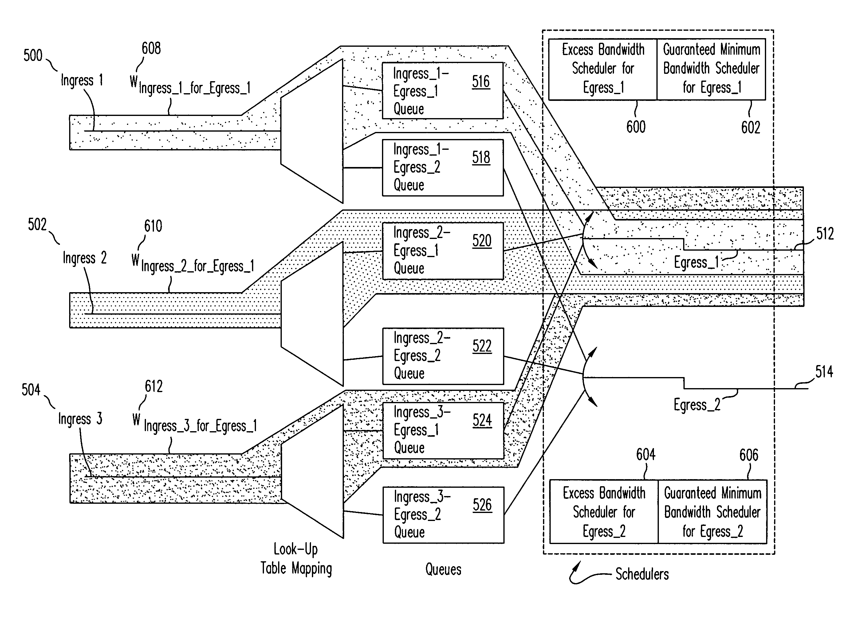
[0070]With reference to the figures, and in particular with reference now to FIG. 5, shown is an expanded view of crossbar switch 136 contained within network node 122. Depicted is that respectively associated with switch ingresses 500-504 into crossbar switch 136 are lookup table mappers 506-510, which map each received data packet to its appropriate switch egress 512-514 dependent upon information contained within the header of each such received data packet in a fashion well-known to those having ordinary scale on the art.

[0071]Switch egresses 512-514 respectively connect with data communications links 174-176. As has been discussed, it is possible that multiple packets, destined for the same data communications link, will arrive at substantially t...


PUM


Abstract

A method and system for use in data communications. The method and system substantially ensure that actual data transmission per unit time from at least one cross-point buffer switch ingress to at least one cross-point buffer switch egress substantially satisfies a designated target amount of actual data transmission per unit time.

Description

[0001]This application is a continuation of, and claims the benefit of priority based on, U.S. patent application Ser. No. 09 / 348,133 entitled “Minimum Bandwidth Guarantee For Cross-Point Buffer Switch” filed Jul. 2, 1999, now U.S. Pat. No. 6,625,160, and naming Hiroshi Suzuki as the inventor. The above-referenced application is hereby incorporated by reference herein in its entirety.CROSS-REFERENCE[0002]The present invention is related to subject matter disclosed in the following application:[0003]1. United States patent application entitled, “Minimum Bandwidth Guarantee For Input-Buffered Packet Switch”, Ser. No. 09 / 348,134, naming Hiroshi Suzuki as the inventor, filed Jul. 2, 1999, and incorporated by reference herein in its entirety.BACKGROUND OF THE INVENTION[0004]1. Field of the Invention[0005]The present invention is related to a method and system to be utilized in data communications. In particular, the present invention is related to a method and system to be utilized in da...

Claims


Application Information

Patent Timeline
Patent Type & Authority Patents(United States)
IPC IPC(8): H04L12/56
CPCH04L47/10H04L47/525H04L47/50H04L49/254H04L49/101H04L49/3018H04L49/205
Inventor SUZUKI
Owner CISCO TECH INC
Why Eureka
Try Eureka