Safety device for elevators

Active Publication Date: 2008-07-15
INVENTIO AG
View PDF12 Cites 38 Cited by
  • Summary
  • Abstract
  • Description
  • Claims
  • Application Information

AI Technical Summary

Benefits of technology

[0010]The safety device according to the present invention has the advantage that it allows, in an excellent manner, an engagement of the safety device in the case of an operating state below the over-speed, that is not so easily possible with the wel

Problems solved by technology

Conventional safety devices are never operated in normal operation of the elevator car below the over-speed, which

Method used


Image

  • Safety device for elevators
  • Safety device for elevators
  • Safety device for elevators

Examples


Embodiment Construction

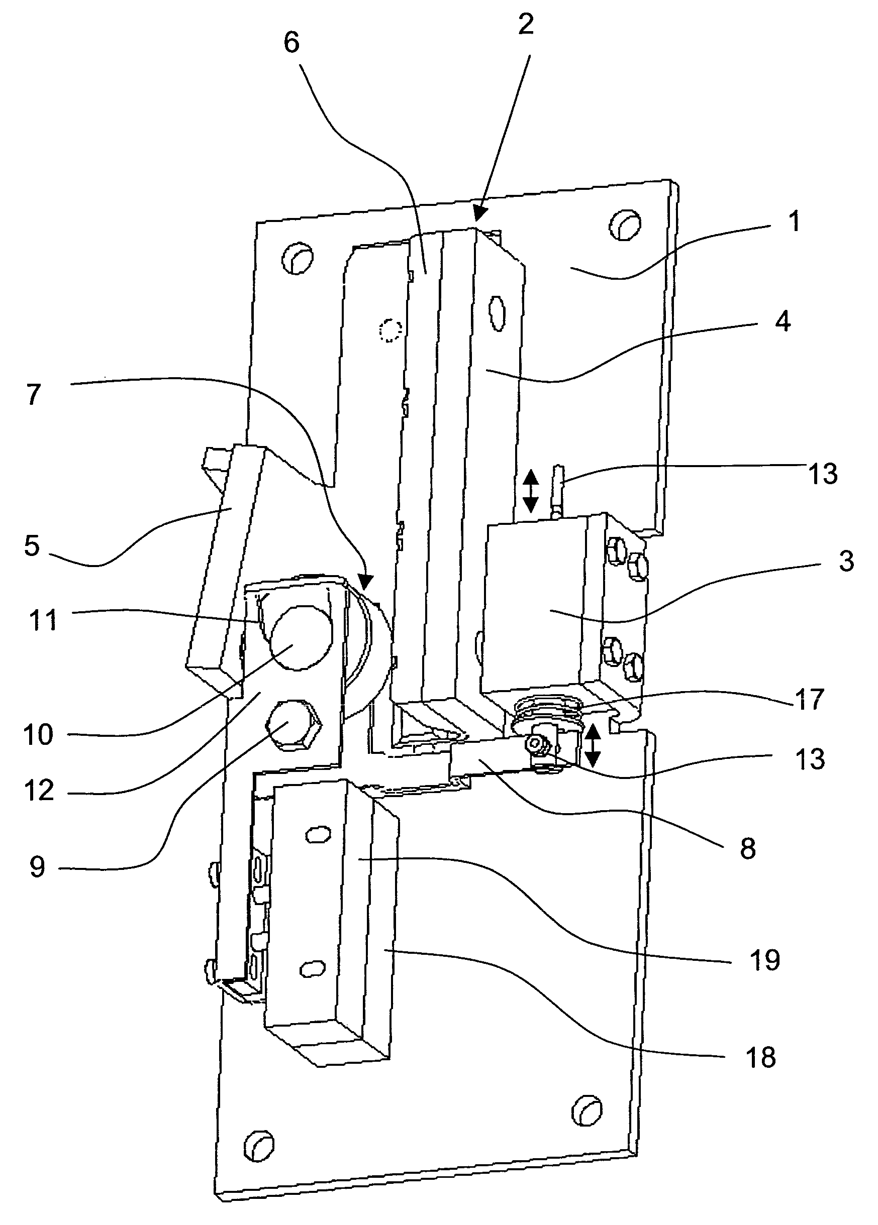
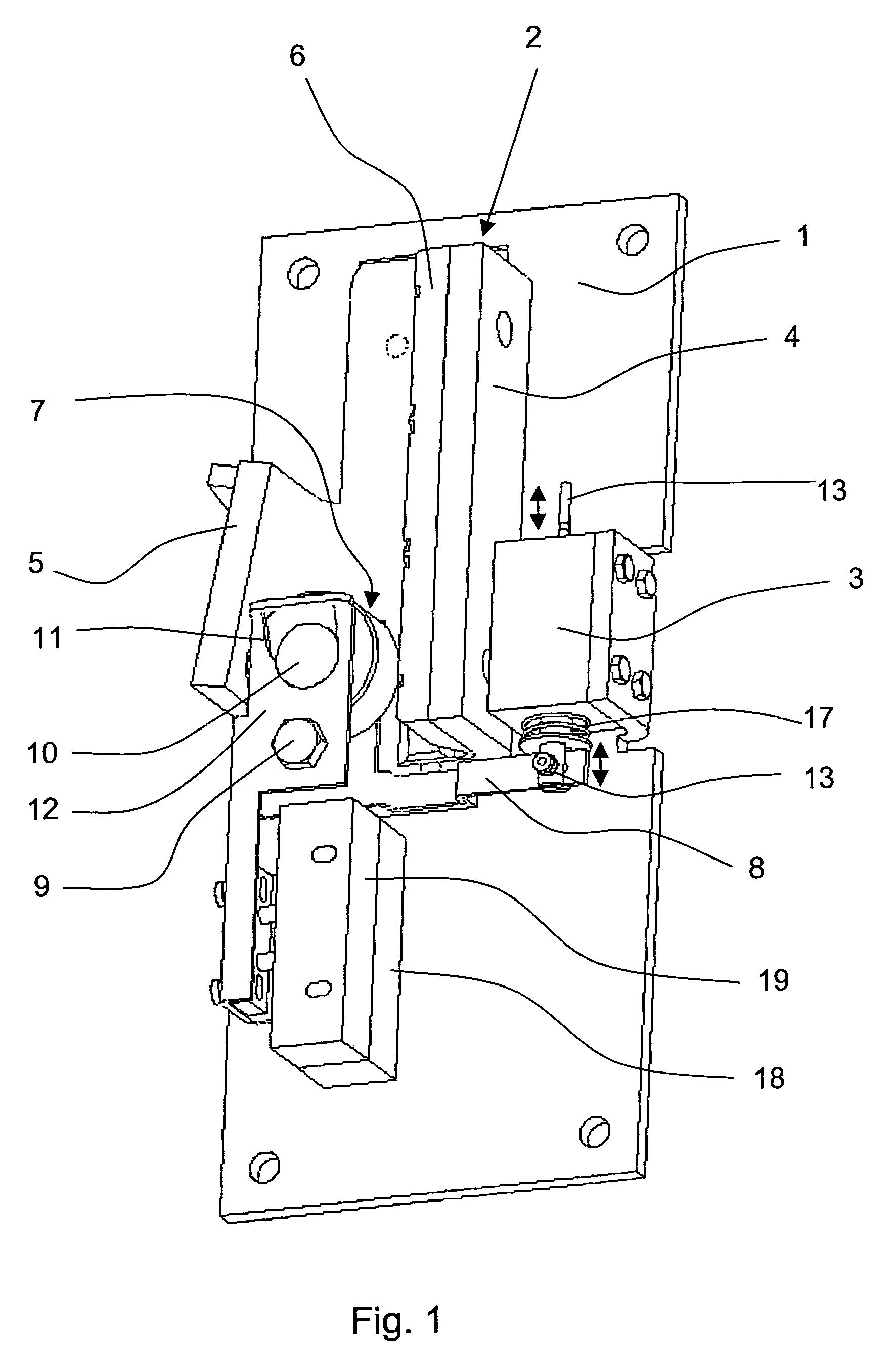
[0034]FIG. 1 shows a base 1, on which a safety device block 2 and an electromagnet 3 of the safety device are firmly installed. The safety device block 2 has a U-shaped cross section formed by two legs 4 and 5, whereby the inside of the leg 4 is provided with a guide and brake lining 6. The safety device is installed on an elevator car (not shown) in an elevator system (not shown) and at the same time is aligned on a guide rail 30 (see FIG. 14), which serves for guiding the elevator car, in such a manner that a guide flange 31 (see FIGS. 4 and 14) of the guide rail 30 is arranged between a braking element, which is developed in the present case as a blocking roller 7, and the guide and brake lining 6.

[0035]In operation, the guide and brake lining 6 touches a guide surface 32 (see FIG. 14) of the guide flange 31. The leg 4 forms together with the guide and brake lining 6 an oblong retaining element for the guide flange 31. With the safety device, the elevator car can be held or respe...


PUM


Abstract

A safety device brakes an elevator car with a guide rail exhibiting an oblong guide flange. The safety device includes a base carrying a retaining element and an abutment with the guide flange positioned therebetween. A mechanism squeezes, when braking, a braking element blocking roller between the guide flange and the abutment. The mechanism, co-operating with an electromagnet, moves the braking element in a controlled way between different positions associated with different operating conditions of the safety device.

Description

BACKGROUND OF THE INVENTION[0001]The present invention relates generally a safety device for elevators to prevent unintended elevator car movement.[0002]For guiding the elevator car in the case of elevators with guide rails, guide shoes, which are arranged at the elevator car, are employed and such guide shoes are developed either as roller guide shoes or as sliding guide shoes. In the first case, rollers are generally provided with so-called two-dimensional or three-dimensional guides, which roll on appropriate guide surfaces of the guide rail. In the second case, slideway linings slide with small free motion along the guide rails, so that they confer to the elevator car during the vertical transport motion a guide in the horizontal plane. Safety devices, which are physically separate from the guide shoes, are fastened to the elevator car and such safety devices operate to engage the guide rail.[0003]The well-known devices of this kind work in the manner that in case of exceeding t...

Claims


Application Information

Patent Timeline
IPC IPC(8): B66B5/12B66B5/18B66B7/04
CPCB66B7/046B66B5/18
Inventor LIEBETRAU, CHRISTOPHSTOCKER, RUEDIROTBOLL, ESBEN
Owner INVENTIO AG
Why Eureka
Try Eureka