Electronic device charging platform and portable electrical outlet enclosure

a charging platform and electronic device technology, applied in the direction of electrical equipment, flexible lead housing, coupling device connections, etc., can solve the problems of unsightly, inconvenient, and unsightly cord tangle, and achieve convenient placement and routing, increase spill resistance, and increase safety

Inactive Publication Date: 2008-07-15
KHORSAND AMIR C
View PDF7 Cites 28 Cited by
  • Summary
  • Abstract
  • Description
  • Claims
  • Application Information

AI Technical Summary

Benefits of technology

[0011]The present invention is directed to an electronic device charging platform and portable electrical outlet enclosure. This platform and enclosure is configured for use with consumer electronics and with a portable electrical outlet device, such as a surge protector or outlet strip. The present invention provides an easily accessible external location for the placement and charging of consumer electronics while providing a safe, convenient, and attractive housing for a portable electrical outlet device and any electrical cords, plugs, transformers, or consumer electronic product charging components that are plugged into the electrical outlets of the portable electrical outlet device.
[0012]The platform and enclosure is comprised of a right half and a left half, which can be attached together to define an interior space configured for placement of the portable electrical outlet device, electrical cords, plugs, transformers, chargers, and the like. The two halves include notches or slots that, when the two halves are joined together, align and form conduits through which cords can be routed to the exterior. The two halves, when attached together, also provide an electronic device charging platform, which is a convenient location to store, charge, and access consumer electronic devices.

Problems solved by technology

For the average home and office, this results in a tangle of cluttered cords around some type of portable electrical outlet device such as a surge protector, power strip, or the like.
Powering and charging of these consumer electronic devices in a safe, suitable, convenient, and attractive location has become a problem.
Not only is this tangle of cords unsightly and inconvenient, but it is also a safety hazard.
Cords are more likely to become entangled or damaged when they are exposed.
When children and pets have ready access to these electrical components they can pull, jerk, or chew on cords damaging the wires and presenting both an electric shock hazard and a fire hazard.
Some enclosures that provide a centralized location for portable electrical outlet devices, connections, and associated wiring do not conceal the connections in an interior space, thereby not solving the safety, access, or aesthetics issues.
Some enclosures do enclose the electrical outlets, connections, and wiring, but do not allow for ease in accessing the connections or for ease in plugging and unplugging components.
A portion of the enclosures currently available are cumbersome or bulky, occupying a large footprint of floor or desk space.

Method used


Image

  • Electronic device charging platform and portable electrical outlet enclosure
  • Electronic device charging platform and portable electrical outlet enclosure
  • Electronic device charging platform and portable electrical outlet enclosure

Examples


first embodiment

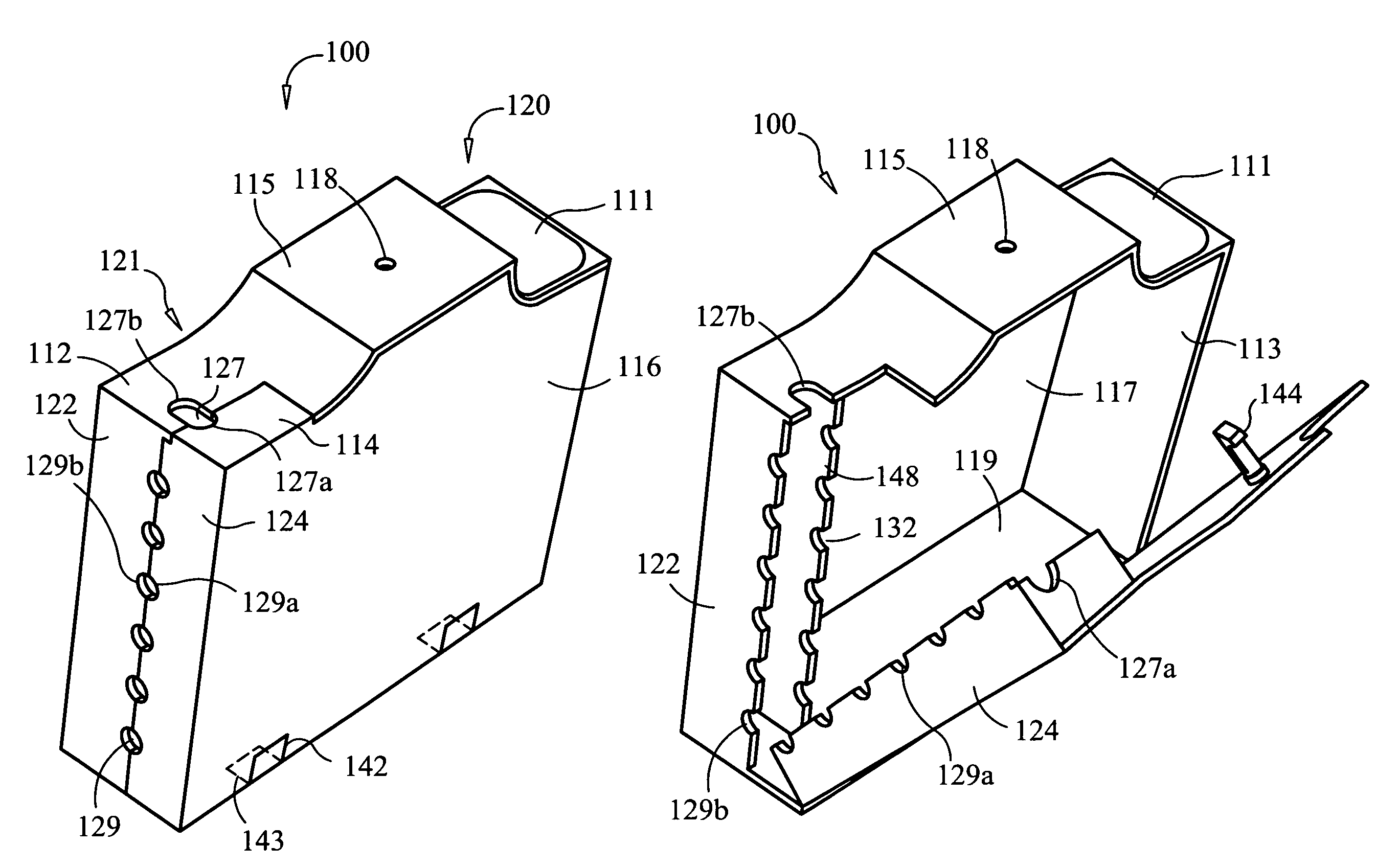
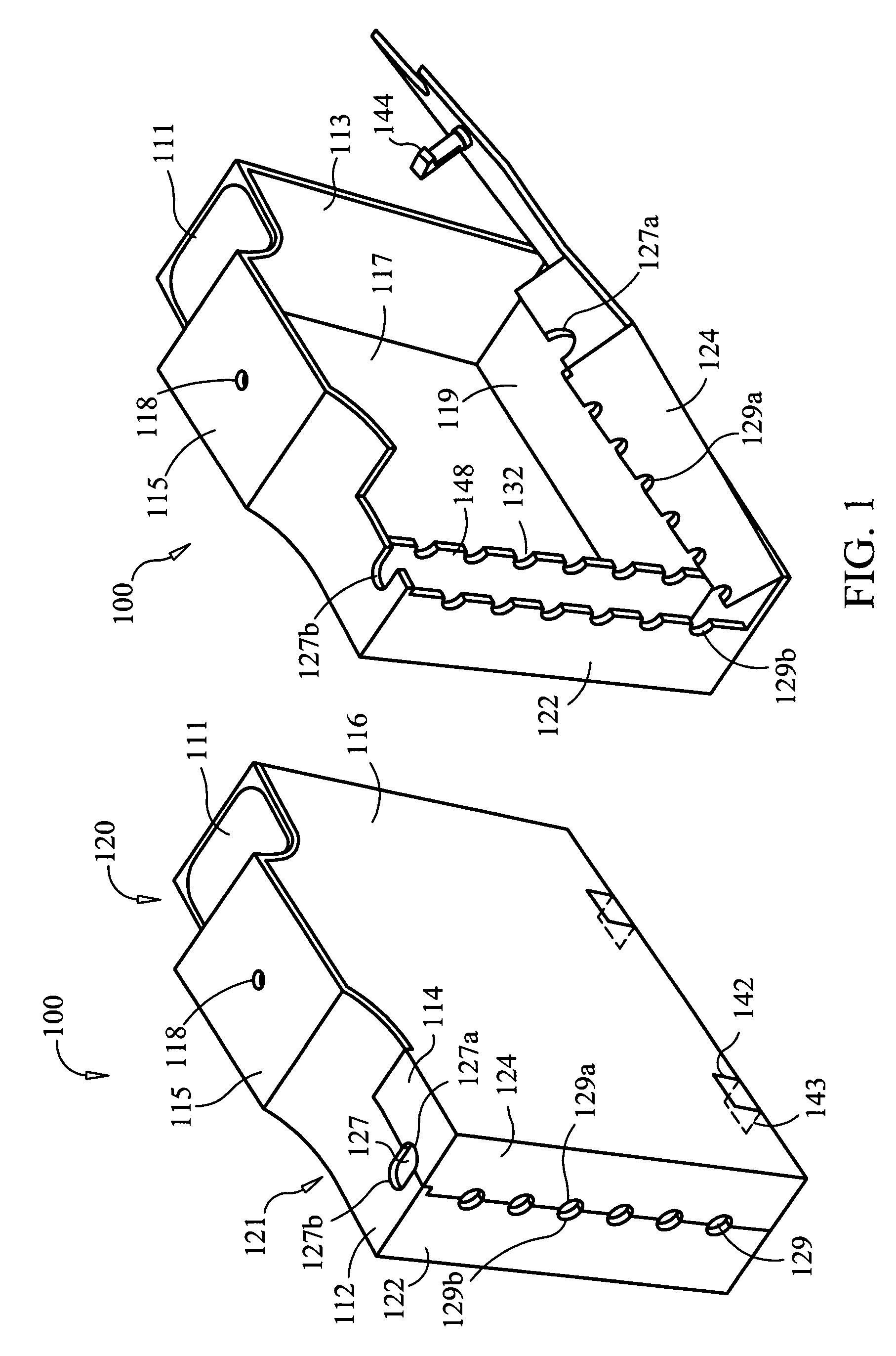
[0037]In the present invention, the connecting mechanism is illustrated as a conventional female-male clip means, a typical female receiving clip 142 (on lower edge of left side wall 116) in operative association with a typical male connector clip 143 (inside interior on left edge of bottom wall 119). This allows the right half and left half to be easily joined together and easily taken apart. Alternatively, other conventional connecting mechanisms as are known in the art can be used to operatively connect the lower edge of left side wall 116 with the left edge of bottom wall 119, such as, for example, hinges, interlocking tabs, or a flexible joint or fold line. It will be appreciated by those skilled in the art that any of a wide variety of different latching mechanisms 144, connecting mechanisms, clip means 142, 143 or hinge means may be utilized without departing from the present invention, and, in addition, that the location, size and orientation of latching mechanism 144 or the...

first exemplary embodiment

[0046]FIG. 6 illustrates a second preferred exemplary embodiment of the electronic device charging platform and portable electrical outlet enclosure of the present invention, generally referred to by the reference numeral 100. The second exemplary embodiment of the electronic device charging platform and portable electrical outlet enclosure 100 is substantially similar to, and functions in a similar manner to, FIG. 1 to FIG. 5, but additionally provides interior organizational securing devices 149 and non-slip mat 151. Furthermore, the second exemplary embodiment of the present invention illustrates the following three variations: 1. a generally more curvilinear shape 153, 154 for elements of the electronic device charging platform and portable electrical outlet enclosure 100, including left side wall 116, right side wall 117, right exterior rear wall 122, left exterior rear wall 124, front wall 113, central top section 115, top forward section 120, and top rearward section 121; 2. ...


PUM


Abstract

An electronic device charging platform and portable electrical outlet enclosure providing a secure, accessible location for the placement and charging of an electronic device on the exterior of the enclosure, while having an interior space to house, use, and conceal a portable electrical outlet device, such as a surge protector or outlet strip, with any power cords and plugs, transformers, or consumer electronic product charging components that are associated with the surge protector is disclosed. The electronic device charging platform and portable electrical outlet enclosure will preferably include a right half and left half, configured so that, as they attach together to create the interior space, slots or notches in each half align to form conduits through which the cords can be routed to the exterior. Additional conduits to the exterior may also be provided for convenience in cord placement and routing.

Description

CROSS-REFERENCE TO RELATED APPLICATION[0001]This application claims the benefit of co-pending U.S. Provisional Patent Application Ser. No. 60 / 775,672, filed on Feb. 22, 2006, which is incorporated herein in its entirety.BACKGROUND OF THE INVENTION[0002]1. Field of the Invention[0003]The present invention relates generally to an apparatus specialized to mount, support, and house an electrical device, and more specifically to an electronic device charging platform and portable electrical outlet enclosure configured for use with electronic devices and with a portable electrical outlet device such as a surge protector or power strip.[0004]2. Description of the Prior Art[0005]The number and types of consumer electronic devices continue to grow phenomenally. These consumer electronic devices, such as cell phones, cameras, music and video players, music and video recorders, wireless headsets, cordless phones, computer accessories, and the like, each come with their own cord, plugs, wiring,...

Claims


Application Information

Patent Timeline
Patent Type & Authority Patents(United States)
IPC IPC(8): H01R13/72
CPCH01R13/506H01R27/02H01R13/72
Inventor KHORSAND, AMIR C.
Owner KHORSAND AMIR C
Why Eureka
Try Eureka