Method of controlling the pressure in a process chamber

a process chamber and pressure control technology, applied in the direction of basic electric elements, electrical equipment, semiconductor/solid-state device testing/measurement, etc., can solve the problems of valve response time preventing accurate pressure control, process pressure variation,

Inactive Publication Date: 2008-07-15
SPTS TECH LTD
View PDF7 Cites 10 Cited by
  • Summary
  • Abstract
  • Description
  • Claims
  • Application Information

AI Technical Summary

Problems solved by technology

However, the nature and the flow rate of the gas vary from one step to another, which causes a variation of the pressure in the process chamber in each step.
However, the duration of each step being variable and relatively short (a few milliseconds to a few seconds), the response time of the valve prevents accurate control of the pressure.

Method used


Image

  • Method of controlling the pressure in a process chamber
  • Method of controlling the pressure in a process chamber
  • Method of controlling the pressure in a process chamber

Examples


Embodiment Construction

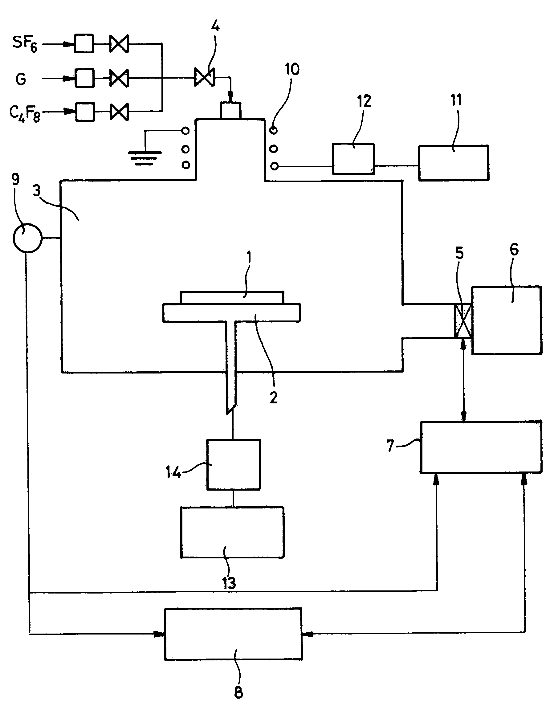
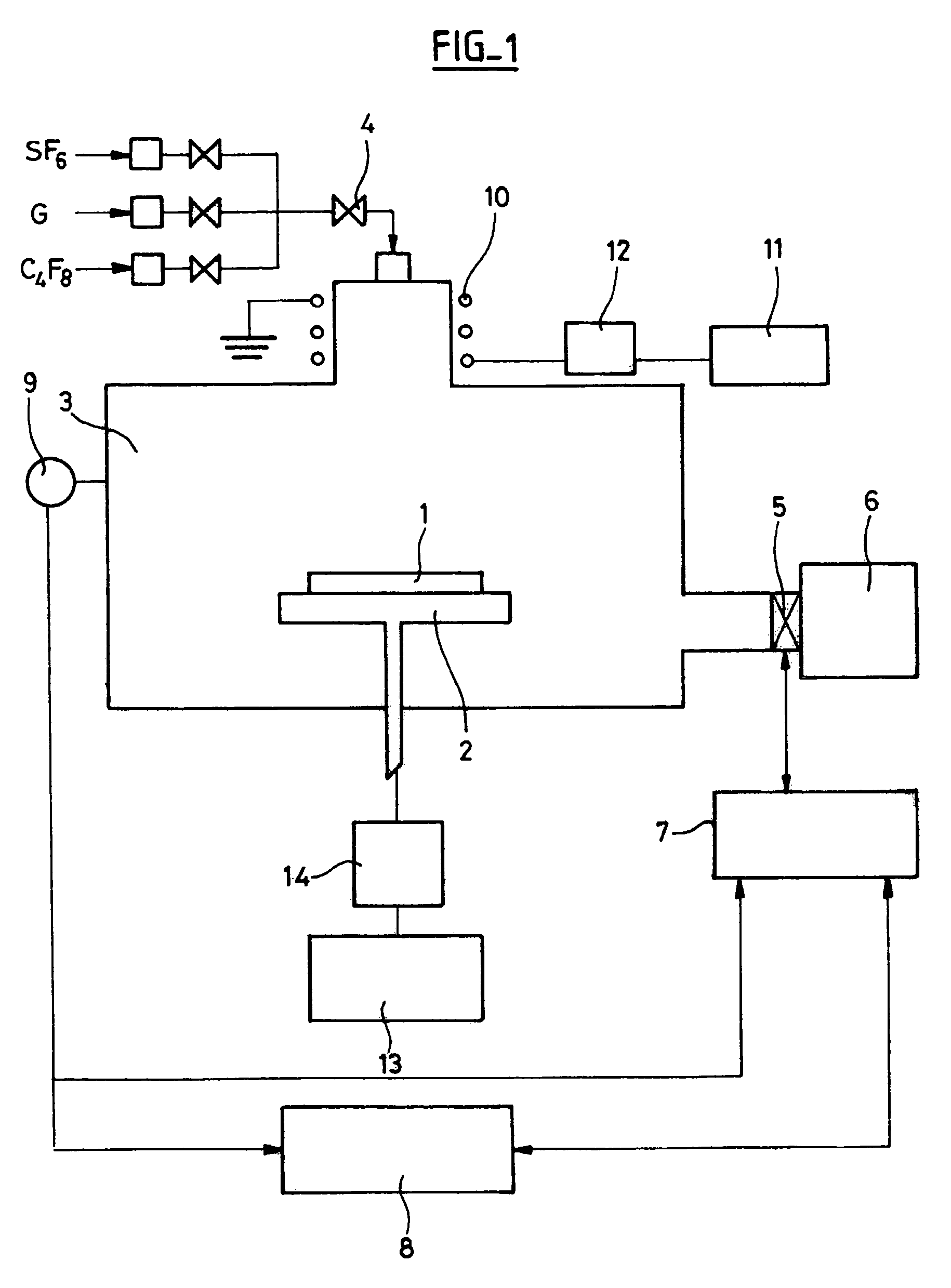
[0031]The installation represented in FIG. 1 is an installation conventionally used for micromachining silicon substrates by plasma etching. The substrate 1 is placed on a support 2 that may be mobile and is disposed in a process chamber 3.

[0032]During the treatment, steps of etching the substrate 1 with a plasma of a fluorinated gas, such as SF6, alternate with surface passivation steps using a plasma of a gas CxFy, such as C4F8, for example. There may also be provision for the introduction of a neutral or cleaning gas G. The treatment gases are introduced into the process chamber 3 by an admission device including a valve 4. The pressure in the process chamber 3 is controlled by means of a throttle valve 5 disposed at the inlet of the vacuum line 6 comprising pumps and associated with a controller 7 controlled by a computer 8. The pressure in the process chamber 3 is measured by apparatus 9 such as a manometer.

[0033]During the etching step, the active gas is excited to form a plas...


PUM


Abstract

The present invention consists in a method of plasma treatment of a semiconductor substrate in a process chamber connected to a vacuum line via a valve, said treatment including a plurality of cycles comprising at least one etching step during which an etching gas is introduced alternating with at least one passivation step during which a passivation gas is introduction into said chamber, which method includes the following operations:(a) a reference pressure Pref is defined at which it is wished to effect the treatment,(b) the position of the valve is fixed during the first etching step,(c) the pressure in the process chamber is allowed to stabilize during n cycles,(d) the pressure in the process chamber is measured during the etching step during m cycles, with m at least equal to 2, and an average pressure value Pc is calculated from the measurements effected,(e) after n+m cycles, the position of the valve is corrected with a view to obtaining a pressure in the process chamber that approximates the reference pressure value Pref,(f) the steps (c) to (e) are repeated until the calculated average pressure Pc is substantially equal to the reference pressure value Pref so that it is no longer necessary to correct the position of the valve.

Description

CROSS-REFERENCE TO RELATED APPLICATIONS[0001]This application is based on French Patent Application No. 0551589 filed Jun. 16, 2005, the disclosure of which is hereby incorporated by reference thereto in its entirety, and the priority of which is hereby claimed under 35 U.S.C. §119.BACKGROUND OF THE INVENTION[0002]1. Field of the Invention[0003]The present invention concerns the field of micromachining semiconductor substrates for the production of micro-electro-mechanical systems (MEMS) or micro-opto-electro-mechanical systems (MOEMS). It relates more particularly to the control and to the regulation of the gas pressure in the process chamber during the different steps of the fabrication of semiconductor components by the alternating plasma etching technique, in particular to the process utilized.[0004]2. Description of the Prior Art[0005]In industrial processes for fabricating or processing products in enclosures supplied with processing gas at very low pressures, it is necessary ...

Claims


Application Information

Patent Timeline
Patent Type & Authority Patents(United States)
IPC IPC(8): H01L21/302H01L21/461
CPCH01L22/26H01L21/30655
Inventor LAUNAY, NICOLAS
Owner SPTS TECH LTD
Why Eureka
Try Eureka