Methods and apparatus for calibrating and controlling output power levels in a broadband communication system

a technology of broadband communication system and output power level, applied in the field of broadband communication, can solve the problems of affecting the quality of cable services offered to the end user, difficult to calibrate and maintain the output power accuracy over a broadband or multi-octave range of operating frequency, and difficulty in completing the task over a broadband range of frequency with the required accuracy, so as to achieve constant output power level

Active Publication Date: 2008-07-15
ARRIS ENTERPRISES LLC
View PDF11 Cites 5 Cited by
  • Summary
  • Abstract
  • Description
  • Claims
  • Application Information

AI Technical Summary

Benefits of technology

[0020]In a further example embodiment of the present invention, a method for controlling output power levels in a broadband communication system is provided. The power level of an intermediate frequency (IF) signal may be varied at a first attenuator. The IF signal from the first attenuator may be frequency converted at a mixer to provide a desired transmit frequency converted signal. The power level of the frequency converted signal may be adjusted at a second attenuator. The signal output may be sampled after the second attenuator in the main broadband signal path, so that the output power level of the signal can be detected. The detected output power level can then be compared with a reference level to obtain a difference signal. The difference signal can then be used in a feedback loop to adjust the power level of the signal output from the first attenuator so that a constant output power level can be maintained.

Problems solved by technology

These requirements present a challenge in the design of the cable router upconverter.
If set incorrectly, the upconverter could disrupt the quality of cable services offered to the end user.
It is difficult to calibrate and maintain this output power accuracy over a broadband or multi-octave range of operating frequencies.
Completing this task over a broadband range of frequencies with the required accuracy is more difficult.
As the number of frequencies increase, the upconverter calibration time increases, which tends to slow down factory output.
While this can solve the problem of maintaining and setting the output power level at a discrete or narrow band of frequencies, it does not work as well in a wideband application as the frequency response of the upconverter and the sensitivity of the detector will vary with frequency of operation.
Such open loop circuits suffer from significant temperature drift when using an analog attenuator or require a broadband digital attenuator with step size equal to that of the transmitter output power step size.
This greatly reduces the candidate parts available which meet the desired power output resolution and all other specification requirements over a large frequency range.
Further, analog or continuous attenuators typically have a nonlinear attenuation versus control signal response making them difficult to represent for calibration over the power level range of the transmitter.
In addition, channel filtering is not possible in broadband RF circuits due to the channel linearity requirements and the number of channels that have to be realized.
However, there will always be a range of unfiltered frequencies around the carrier.
This nonlinear response increases calibration time.
Further, analog attenuators are difficult to temperature compensate.
As discussed above in connection with FIG. 1, an analog attenuator exhibits nonlinear response over frequency and output level range and is difficult to calibrate.
Further, analog attenuators are difficult to temperature compensate over frequency.
This system does not allow for a digital attenuator to be used in a continuous control loop, since a digital attenuator can only be used to make adjustments in discrete step sizes (e.g., 1 dB, 2 dB, etc.).
Further, such a system requires many frequency band calibrations to obtain required output level accuracy.

Method used


Image

  • Methods and apparatus for calibrating and controlling output power levels in a broadband communication system
  • Methods and apparatus for calibrating and controlling output power levels in a broadband communication system
  • Methods and apparatus for calibrating and controlling output power levels in a broadband communication system

Examples


Embodiment Construction

[0029]The ensuing detailed description provides exemplary embodiments only, and is not intended to limit the scope, applicability, or configuration of the invention. Rather, the ensuing detailed description of the exemplary embodiments will provide those skilled in the art with an enabling description for implementing an embodiment of the invention. It should be understood that various changes may be made in the function and arrangement of elements without departing from the spirit and scope of the invention as set forth in the appended claims.

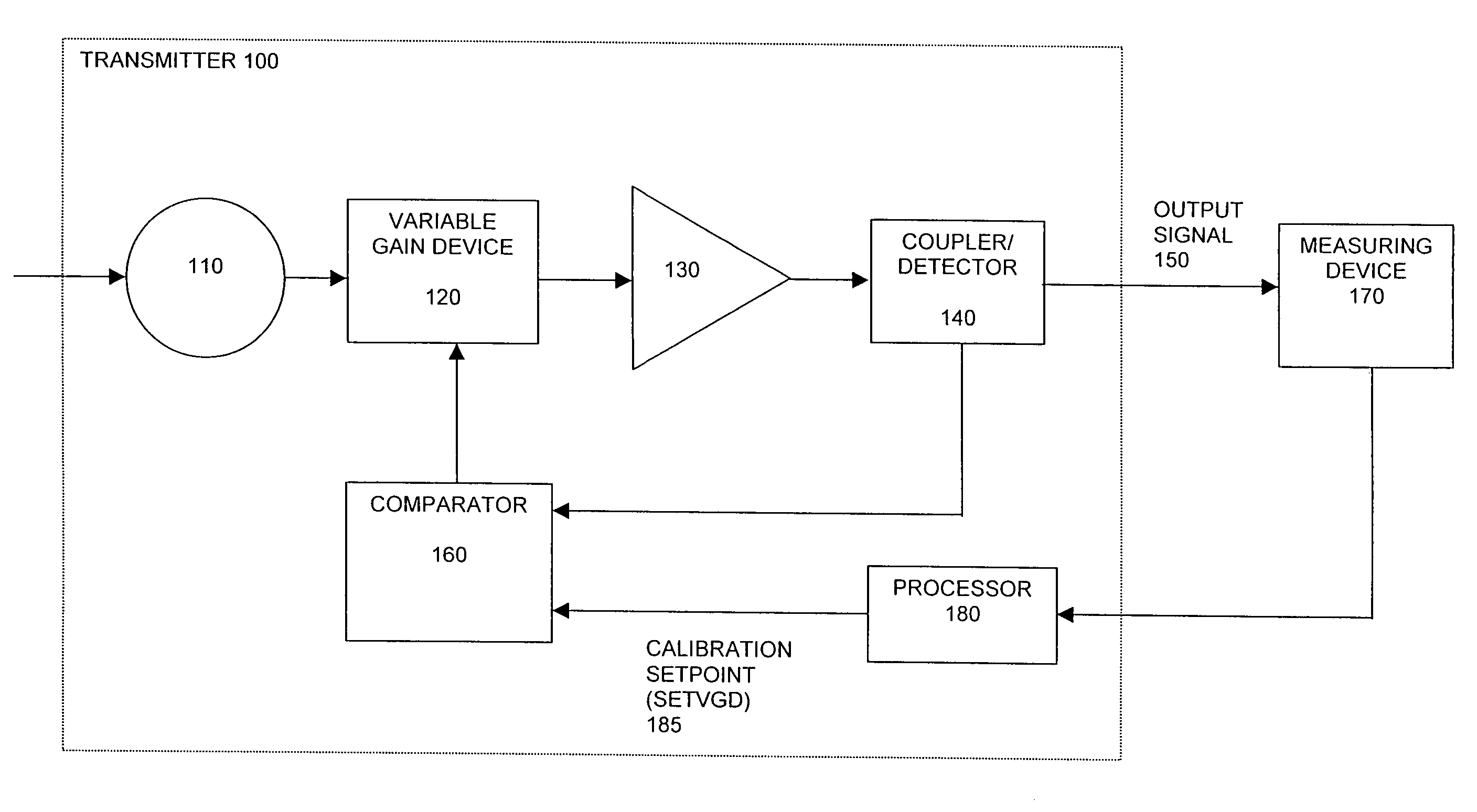
[0030]The present invention relates to methods and apparatus for calibrating and controlling output power levels of a broadband signal in a broadband communication system. In an example embodiment of the present invention, methods and apparatus for calibrating a transmitter and setting output power levels of a broadband signal in a broadband communications system are provided. The broadband signal may comprise one of an RF signal or microwave ...


PUM


Abstract

The present invention provides methods and apparatus for calibrating and controlling output power levels in a broadband communication system. The power level of an intermediate frequency (IF) signal may be varied at a first attenuator. The IF signal from the first attenuator may be frequency converted at a mixer to provide a desired transmit frequency converted signal. The power level of the frequency converted signal may be adjusted at a second attenuator. The signal may be sampled after the second attenuator in order to detect its output power level. The detected output power level may be compared with a reference level to obtain a difference signal. The difference signal may be used in a feedback loop to adjust the power level of the signal output from the first attenuator so that a constant output power level is maintained. Methods and apparatus for calibrating output power levels are also provided.

Description

BACKGROUND OF THE INVENTION[0001]The present invention relates to the field of broadband communications. More specifically, the present invention relates to methods and apparatus for calibrating and controlling power output levels in a broadband communication system.[0002]Hybrid fiber coaxial (HFC) networks are used by cable companies to provide services such as analog and / or digital video, video on demand, data communications, and telephony services to the home. These networks utilize a headend system, often referred to as a cable router or CMTS (cable modem termination system), to send information through an RF link from the cable plant to the end user. The HFC network requires that the cable router be capable of operating over a broad range of downstream frequencies, such as 50-860 MHz, and a wide range of output power levels, such as +48 to +61 dBmV.[0003]These requirements present a challenge in the design of the cable router upconverter. The upconverter is the RF interface bet...

Claims


Application Information

Patent Timeline
Patent Type & Authority Patents(United States)
IPC IPC(8): H04B17/00H01Q11/12
CPCH03G3/3084H04W52/36H04B2001/0416
Inventor SMENTEK, DAVID J.WILSON, RONALD E.
Owner ARRIS ENTERPRISES LLC
Why Eureka
Try Eureka