Direct conversion RF transceiver with automatic transmit power control

a transceiver and automatic transmission technology, applied in the field of communication systems, can solve the problems of power amplifiers generating significant temperatures affecting device reliability and/or operation, and engineers are faced with a very difficult design challenge to develop such a wireless communication device, so as to reduce the output power level of the power amplifier, reduce the input gain level, and maintain the effect of power level

Inactive Publication Date: 2007-01-02
AVAGO TECH INT SALES PTE LTD
View PDF5 Cites 4 Cited by
  • Summary
  • Abstract
  • Description
  • Claims
  • Application Information

AI Technical Summary

Benefits of technology

[0012]A radio frequency (RF) variable gain amplifier (VGA) includes a power amplifier in a direct conversion radio transceiver that includes a gain determination module that reduces an input gain level to the power amplifier (PA) to reduce an output power level of the power amplifier according to temperature indications. In one embodiment of the invention, the gain determination module adjusts input gain levels to compensate for power reduction that occurs as a result of increased temperatures so as to maintain a constant output power level. In another embodiment of the invention, or alternative, in another mode of operation of the invention, the gain determination module reduces the input gain level to the power amplifier to prompt it to produce lower output power so as to cause it to reduce its operational temperature and, therefore, to maintain highest reliability.

Problems solved by technology

As the demand for enhanced performance (e.g., reduced interference and / or noise, improved quality of service, compliance with multiple standards, increased broadband applications, etc.), smaller sizes, lower power consumption, and reduced cost, wireless communication device engineers are faced with a very difficult design challenge to develop such a wireless communication device.
One problem with integrating radio transceiver circuits with power amplifiers, however, is that the power amplifiers generate significant temperatures that affect device reliability and / or operation.

Method used


Image

  • Direct conversion RF transceiver with automatic transmit power control
  • Direct conversion RF transceiver with automatic transmit power control
  • Direct conversion RF transceiver with automatic transmit power control

Examples


Embodiment Construction

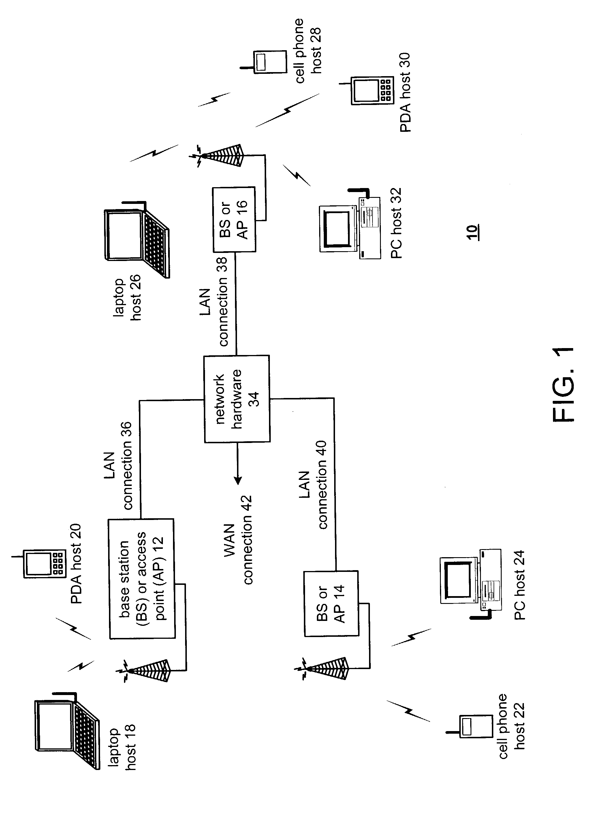
[0027]FIG. 1 is a schematic block diagram illustrating a communication system 10 that includes a plurality of base stations and access points 12–16, a plurality of wireless communication devices 18–32 and a network hardware component 34. The wireless plurality of communication devices 18–32 may be laptop host computers 18 and 26, personal digital assistant hosts 20 and 30, personal computer hosts 24 and 32 and / or cellular telephone hosts 22 and 28. The details of the wireless communication devices will be described in greater detail with reference to FIG. 2.

[0028]The base stations or access points 12–16 are operably coupled to the network hardware component 34 via local area network (LAN) connections 36, 38 and 40. The network hardware component 34, which may be a router, switch, bridge, modem, system controller, etc., provides a wide area network (WAN) connection 42 for the communication system 10. Each of the plurality of base stations or access points 12–16 has an associated ante...


PUM


Abstract

A single chip radio transceiver includes circuitry that enables received RF signals to be down-converted to baseband frequencies and baseband signals to be up-converted to RF signals prior to transmission without requiring conversion to an intermediate frequency. The circuitry includes a low noise amplifier, automatic frequency control circuitry for aligning the LO frequency with the frequency of the received RF signals, received signal strength indicators for adjusting frontal and rear amplification stages accordingly, and, finally, filtering circuitry to filter high and low frequency interfering signals, including DC offset. A radio frequency (RF) variable gain amplifier (VGA) includes a power amplifier in a direct conversion radio transceiver that includes a gain determination module that reduces an input gain level to the power amplifier to adjust the output power level of the power amplifier according to temperature indications to maintain reliable operation or power level indications to maintain a constant output power level.

Description

CROSS-REFERENCE TO RELATED APPLICATION(S)[0001]This application claims priority to under 35 U.S.C. §120 and incorporates by reference and is a continuation-in-part of U.S. Utility Application entitled, “Local Oscillator Frequency Correction in a Direct Conversion RF Transceiver” having a Ser. No. of 10 / 255,378 and a filing date of Sept. 26, 2002, and U.S. Utility Application entitled, “A Direct Conversion RF Transceiver for Wireless Communications”, having a Ser. No. of 10 / 052,870 and a filing date of Jan. 18, 2002, and U.S. Utility Application entitled, “RF Variable Gain Amplifier with Fast Acting DC Offset Cancellation”, having a Ser. No. of 10 / 274,655 and a filing date of Oct. 21, 2002.BACKGROUND OF THE INVENTION [0002]1. Field of the Invention[0003]This invention relates generally to communication systems and, more particularly, to Radio Frequency (RF) signal amplification within wireless devices operating in wireless communication systems.[0004]2. Background of the Invention[00...

Claims


Application Information

Patent Timeline
Patent Type & Authority Patents(United States)
IPC IPC(8): H04B1/40H03G3/30H03J7/04H04B1/04H04B1/30
CPCH03G3/3042H03J7/04H04B1/30H04B1/408H04B1/04H04B2001/0416
Inventor SHI, ZHONGMINGROFOUGARAN, AHMADREZABEHZAD, ARYA
Owner AVAGO TECH INT SALES PTE LTD
Why Eureka
Try Eureka