Fiber amplifier and control method thereof

a technology of fiber amplifiers and control methods, applied in the direction of electromagnetic repeaters, instruments, active medium materials, etc., can solve the problems of increasing costs, and achieve the effects of reducing transient effects, constant output power level, and constant gain

Inactive Publication Date: 2006-05-02
ELECTRONICS & TELECOMM RES INST
View PDF17 Cites 13 Cited by
  • Summary
  • Abstract
  • Description
  • Claims
  • Application Information

AI Technical Summary

Benefits of technology

[0011]It is an advantage of the present invention to realize the AGC and ALC functions through a simple circuit, and obtain a constant output for each channel irrespective of the number of input channels and input power.
[0012]It is another advantage of the present invention to suppress transient effects at the output terminal.
[0013]In one aspect of the present invention, a fiber amplifier comprises a first stage amplifier including a first fiber and a first pump laser diode, the first stage amplifier amplifying an input light by a predetermined gain; a second stage amplifier including a second fiber and a second pump laser diode, the second stage amplifier receiving an output light of the first stage amplifier and generating a Raman gain; a third stage amplifier including a third fiber and a third pump laser diode, the third stage amplifier amplifying the light output from the second stage amplifier by a predetermined gain; and an automatic gain controller for receiving part of the light input to the first stage amplifier to check whether an input light power is varied, and when the input light power is varied, controlling pump powers of the second and third pump laser diodes respectively of the second and third stage amplifiers to obtain constant gain, the pump powers of the second and third pump laser diodes being controlled in a state where a pump light of the first pump laser diode of the first stage amplifier is fixed.
[0014]In another aspect of the present invention, a fiber amplifier comprises a first stage amplifier including a first fiber and a first pump laser diode, the first stage amplifier amplifying an input light by a predetermined gain; a second stage amplifier including a second fiber and a second pump laser diode, the second stage amplifier receiving an output light of the first stage amplifier and generating a Raman gain; a third stage amplifier including a third fiber and a third pump laser diode, the third stage amplifier amplifying the light output from the second stage amplifier by a predetermined gain; and an automatic level controller for receiving part of the light input to the first stage amplifier to check whether an input light power of a specific channel is varied, and when the input light power of the specific channel is varied, controlling pump powers respectively of the second and third pump laser diodes of the second and third stage amplifiers to obtain a constant output power level, the pump powers of the second and third pump laser diodes being controlled in a state where a pump light of the first pump laser diode of the first stage amplifier is fixed.
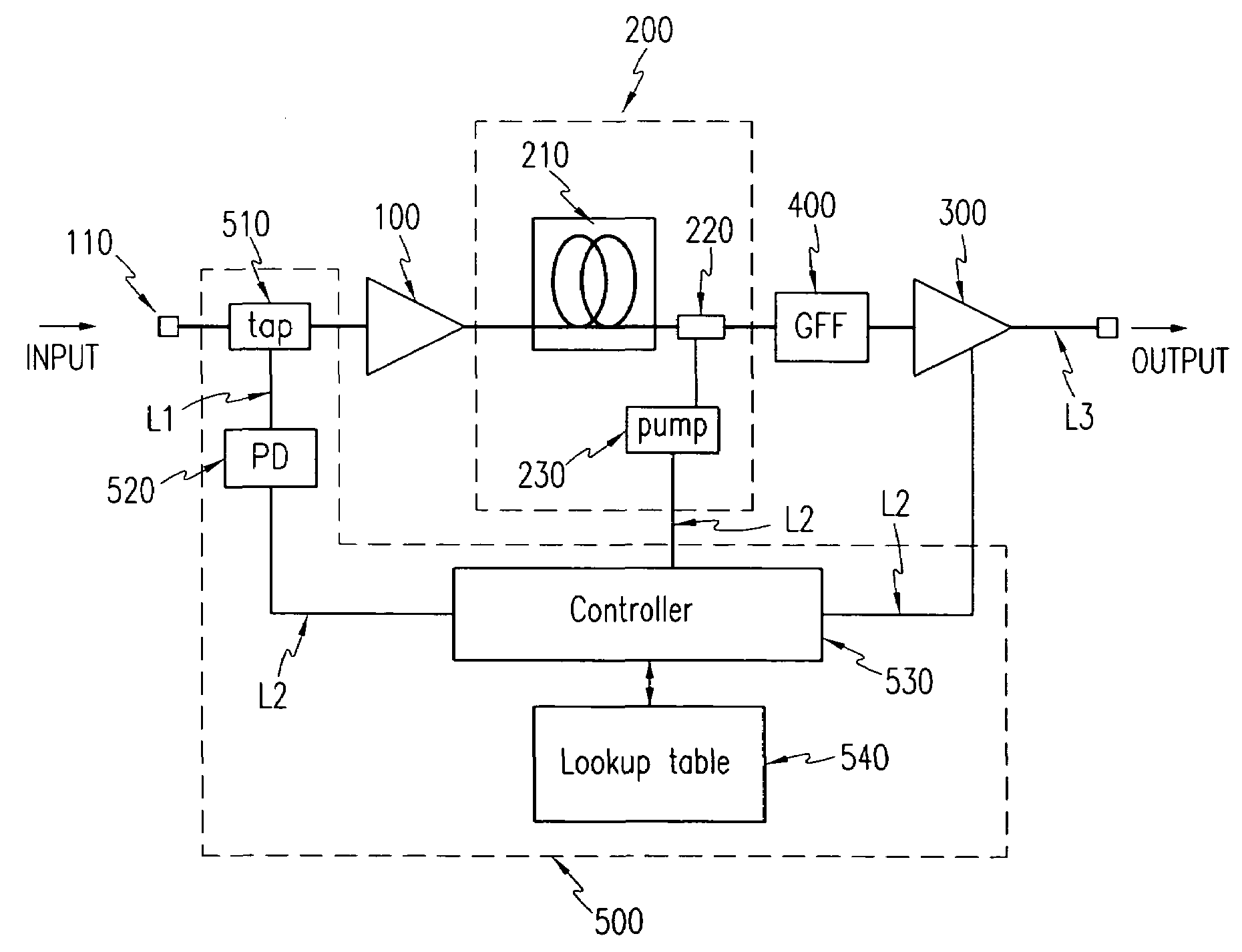
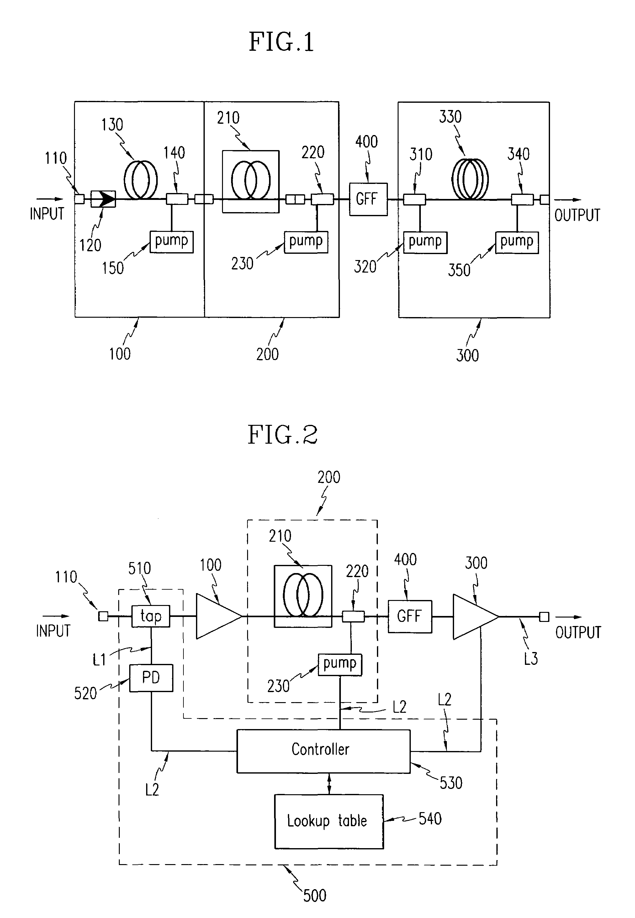
[0015]In still another aspect of the present invention, a fiber amplifier comprises a first stage amplifier including a first fiber and a first pump laser diode, the first stage amplifier amplifying an input light by a predetermined gain; a second stage amplifier including a second fiber and a second pump laser diode, the second stage amplifier receiving an output light of the first stage amplifier and generating a Raman gain; a third stage amplifier including a third fiber and a third pump laser diode, the third stage amplifier amplifying the light output from the second stage amplifier by a predetermined gain; an automatic gain controller for receiving part of the light input to the first stage amplifier to check whether an input light power is varied, and when the input light power is varied, controlling pump powers of the second and third pump laser diodes respectively of the second and third stage amplifiers to obtain constant gains, the pump powers of the second and third pump laser diodes being controlled in a state where a pump light of the first pump laser diode of the first stage amplifier is fixed; and an automatic level controller for receiving part of the light input to the first stage amplifier to check whether an input light power of a specific channel is varied, and when the input light power of the specific channel is varied, controlling pump powers of the second and third pump laser diodes respectively of the second and third stage amplifiers to obtain a constant output power level, the pump powers of the second and third pump laser diodes being controlled in a state where a pump light of the first pump laser diode of the first stage amplifier is fixed.
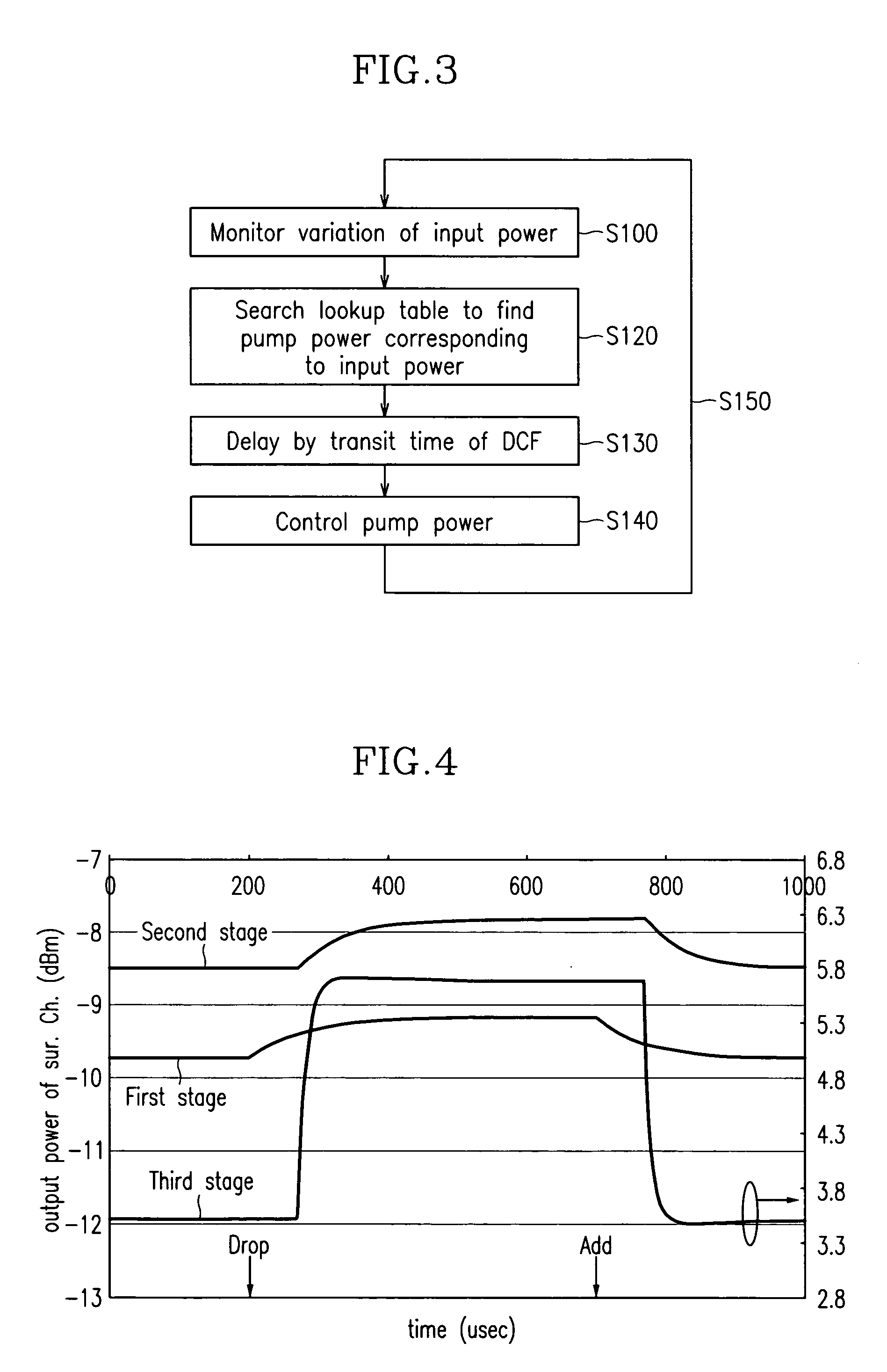
[0016]In still yet another aspect of the present invention, a control method of a fiber amplifier including a first stage amplifier that has a first fiber and a first pump laser diode for amplifying an input light by a predetermined gain, a second stage amplifier that has a second fiber and a second pump laser diode for receiving an output light of the first stage amplifier and generating a Raman gain, and a third stage amplifier that has a third fiber and a third pump laser diode for amplifying the light output from the second stage amplifier by a predetermined gain, comprises (a) monitoring variations in an input power of a light input to the first stage amplifier; (b) finding a pump power corresponding to the varied input power; and (c) controlling the second and third pump laser diodes based on the found pump powers to obtain a constant gain.

Problems solved by technology

However, since it is necessary, in order to realize AGC and ALC with the use of this method, to provide an additional circuit for each gain block and control gain and output optical power levels so that they remain constant, a corresponding amount of complexity in the circuit results to thereby increase costs.

Method used


Image

  • Fiber amplifier and control method thereof
  • Fiber amplifier and control method thereof
  • Fiber amplifier and control method thereof

Examples


Embodiment Construction

[0027]In the following detailed description, only the preferred embodiments of the invention have been shown and described, simply by way of illustration of the best mode contemplated by the inventor(s) of carrying out the invention. As will be realized, the invention is capable of modification in various obvious respects, all without departing from the invention. Accordingly, the drawings and description are to be regarded as illustrative in nature, and not restrictive.

[0028]FIG. 1 shows a basic configuration of a fiber amplifier according to a preferred embodiment of the present invention.

[0029]As shown in the drawing, the fiber amplifier has a 3-stage amplifier configuration.

[0030]That is, the fiber amplifier comprises an EDFA 100 which is a first stage amplifier configured to effect high population density inversion, a DCRA (dispersion compensating Raman amplifier) 200 which is a second stage amplifier for performing backward pumping of DCF (dispersion compensating fiber) to obt...


PUM

PropertyMeasurementUnit
wavelengthaaaaaaaaaa
Raman gainaaaaaaaaaa

Abstract

A method for realizing, in a fiber amplifier with three stages of amplifiers, automatic gain control in which a constant gain is obtained when channels are varied, and automatic level control in which a constant output per channel is obtained when a light power is varied because of variations in span loss. A light power or another light power of a specific wavelength is monitored to determine when variations in these light powers take place, current values of pump laser diodes appropriate for an input is read from a lookup table, and pump laser diodes are driven. During this operation, a pump power of the first stage amplifier is constantly maintained, and those of the second or third stage amplifier are controlled.

Description

CROSS REFERENCE TO RELATED APPLICATION[0001]This application claims priority to and the benefit of Korea Patent Application No. 2003-16113 filed on Mar. 14, 2003 in the Korean Intellectual Property Office, the content of which is incorporated herein by reference.BACKGROUND OF THE INVENTION[0002](a) Field of the Invention[0003]The present invention relates to an optical power amplifier and a control method thereof. More specifically, the present invention relates to a method for controlling an optical gain and an output power level in a fiber amplifier with a 3-stage optical gain block.[0004](b) Description of the Related Art[0005]As a result of fast developments in Internet technology, the demand for enhanced transmission capacity has greatly increased. WDM (wavelength division multiplexing) optical transmission systems have been proposed as a way to satisfy such a demand for greater transmission capacity.[0006]An essential requirement of the optical transmission system is the fiber...

Claims


Application Information

Patent Timeline
Patent Type & Authority Patents(United States)
IPC IPC(8): H04B10/12H01S3/00G02F1/35G02B6/00H01S3/06H01S3/067H01S3/0941H01S3/10H01S3/13H01S3/16H01S3/23H01S3/30H04B10/07H04B10/2525H04B10/29H04B10/293H04B10/294H04B10/564H04B10/572H04J14/00H04J14/02
CPCH01S3/06758H04B10/296H01S3/0941H01S3/10015H01S3/10069H01S3/1301H04B2210/003H01S3/1608H01S3/2375H01S3/302H01S2301/04H01S3/1305H01S3/0078H01S3/1001G02B6/00
Inventor CHANG, SUN-HYOKCHUNG, HEE-SANGHAN, JIN-SOOKIM, SEUNG-KWANLEE, WON-KYOUNGCHU, MOO-JUNG
Owner ELECTRONICS & TELECOMM RES INST
Why Eureka
Try Eureka