Gas turbine control system and method for single-shaft combined cycle plant

a control system and single-shaft technology, applied in the direction of machines/engines, mechanical energy handling, mechanical equipment, etc., can solve the problems of sudden decrease of the vacuum degree of the condenser, erroneous recognition of the unchanged and the inability to control the output of steam turbines. to achieve the effect of constant gas turbine outpu

Inactive Publication Date: 2010-12-02
MITSUBISHI POWER LTD
View PDF6 Cites 13 Cited by
  • Summary
  • Abstract
  • Description
  • Claims
  • Application Information

AI Technical Summary

Benefits of technology

[0015]The present invention provides the advantage of maintaining a constant gas turbine output without requiring a complicated procedure on site and without being affected by variations in the output of the steam turbine during switching between reverse washing and normal washing.

Problems solved by technology

In a single-shaft combined cycle plant, when a condenser is switched between normal washing and reverse washing, the flow of sea water stops momentarily, with the result that the degree of vacuum of the condenser decreases suddenly.
The decreased degree of vacuum of the condenser decreases the output of a steam turbine, thus causing a situation where the output of a generator decreases.
The steam turbine output is conventionally calculated with correction based on the degree of vacuum of the condenser, but if the degree of vacuum of the condenser changes suddenly, an instrument cannot follow the change in degree of vacuum, and the steam turbine output may be erroneously recognized to remain unchanged by calculation despite the fact that the steam turbine output has actually decreased.
This prevents proper control of the gas turbine and poses the risk of malfunctions of various equipment in the power plant.

Method used


Image

  • Gas turbine control system and method for single-shaft combined cycle plant
  • Gas turbine control system and method for single-shaft combined cycle plant
  • Gas turbine control system and method for single-shaft combined cycle plant

Examples


Embodiment Construction

[0024]An embodiment of a gas turbine control system and method for a single-shaft combined cycle plant according to the present invention will be described below with reference to the drawings.

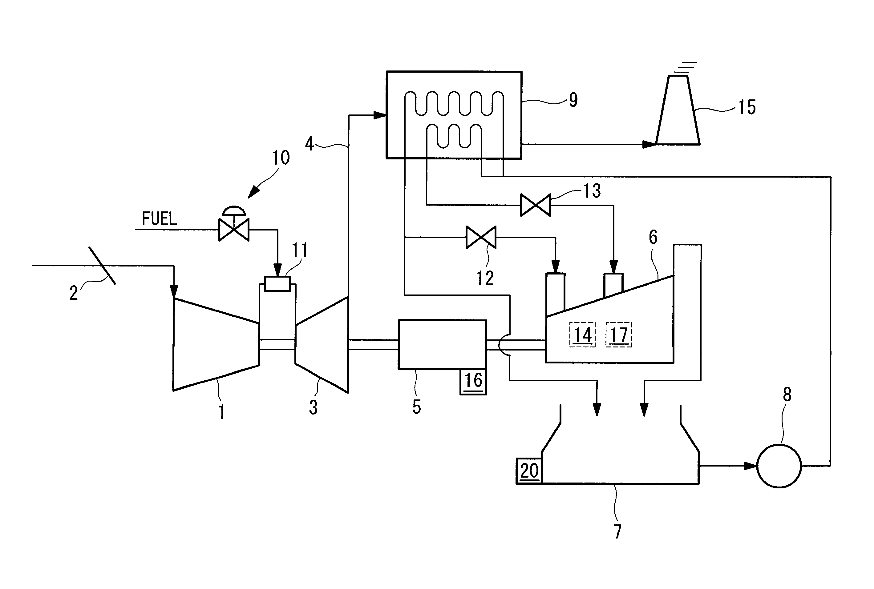
[0025]FIG. 1 is a schematic configuration diagram of a single-shaft combined cycle power plant according to an embodiment of the present invention. The single-shaft combined cycle power plant includes a compressor 1, a gas turbine 3, a generator 5, a steam turbine 6, a condenser 7, a condensate pump 8, a waste heat recovery boiler 9, a combustor 11, a main steam regulating valve 12, and a steam regulating valve 13. The gas turbine 3, the steam turbine 6, and the generator 5 have rotating shafts thereof coupled together and are configured such that the gas turbine 3 and the steam turbine 6 are directly connected to the single generator 5. In addition, a pipe for supplying, for example, air to the compressor 1 is equipped with a compressor inlet guide vane control valve (IGV control valve) 2 for...


PUM


Abstract

An object is to maintain a constant gas turbine output without requiring a complicated procedure on site and without being affected by variations in the output of a steam turbine during a reverse-washing/normal-washing switching period of a condenser. A gas turbine control system for a single-shaft combined cycle plant generates a gas turbine output command using a parameter reflecting a gas turbine output during a reverse-washing/normal-washing switching period of a condenser and generates the gas turbine output command on the basis of a generator output command and a steam turbine output during a period other than the reverse-washing/normal-washing switching period of the condenser.

Description

TECHNICAL FIELD[0001]The present invention relates to a single-shaft combined cycle plant in which rotating shafts of a gas turbine, a steam turbine, and a generator are coupled together, and particularly to a gas turbine control system and method for output control of the gas turbine.BACKGROUND ART[0002]In a single-shaft combined cycle plant, when a condenser is switched between normal washing and reverse washing, the flow of sea water stops momentarily, with the result that the degree of vacuum of the condenser decreases suddenly. The decreased degree of vacuum of the condenser decreases the output of a steam turbine, thus causing a situation where the output of a generator decreases.[0003]The steam turbine output is conventionally calculated with correction based on the degree of vacuum of the condenser, but if the degree of vacuum of the condenser changes suddenly, an instrument cannot follow the change in degree of vacuum, and the steam turbine output may be erroneously recogni...

Claims


Application Information

Patent Timeline
Patent Type & Authority Applications(United States)
IPC IPC(8): H02K7/18F02C9/00
CPCF01K23/16Y02E20/16F02C9/28F02C6/18F01K13/02F05D2220/72F01K23/101
Inventor YAMASHITA, HIDEKAZUNAGATA, SHOICHIMASAKI, MORIHIKO
Owner MITSUBISHI POWER LTD
Why Eureka
Try Eureka