Switching power supply controller and semiconductor device used for the same

Inactive Publication Date: 2010-02-11
PANASONIC CORP
View PDF8 Cites 15 Cited by
  • Summary
  • Abstract
  • Description
  • Claims
  • Application Information

AI Technical Summary

Benefits of technology

[0017]According to the present invention, the peak value of drain current passing through the switching element can be kept constant regardless of an input voltage. Thus it is possible to obtain a power supply with constant output charact

Problems solved by technology

However, the switching power supply controller disclosed in Japanese Patent Laid-Open No. 2

Method used


Image

  • Switching power supply controller and semiconductor device used for the same
  • Switching power supply controller and semiconductor device used for the same
  • Switching power supply controller and semiconductor device used for the same

Examples


first embodiment

[0031]The following will describe a switching power supply controller according to a first embodiment of the present invention and a semiconductor device used for the same.

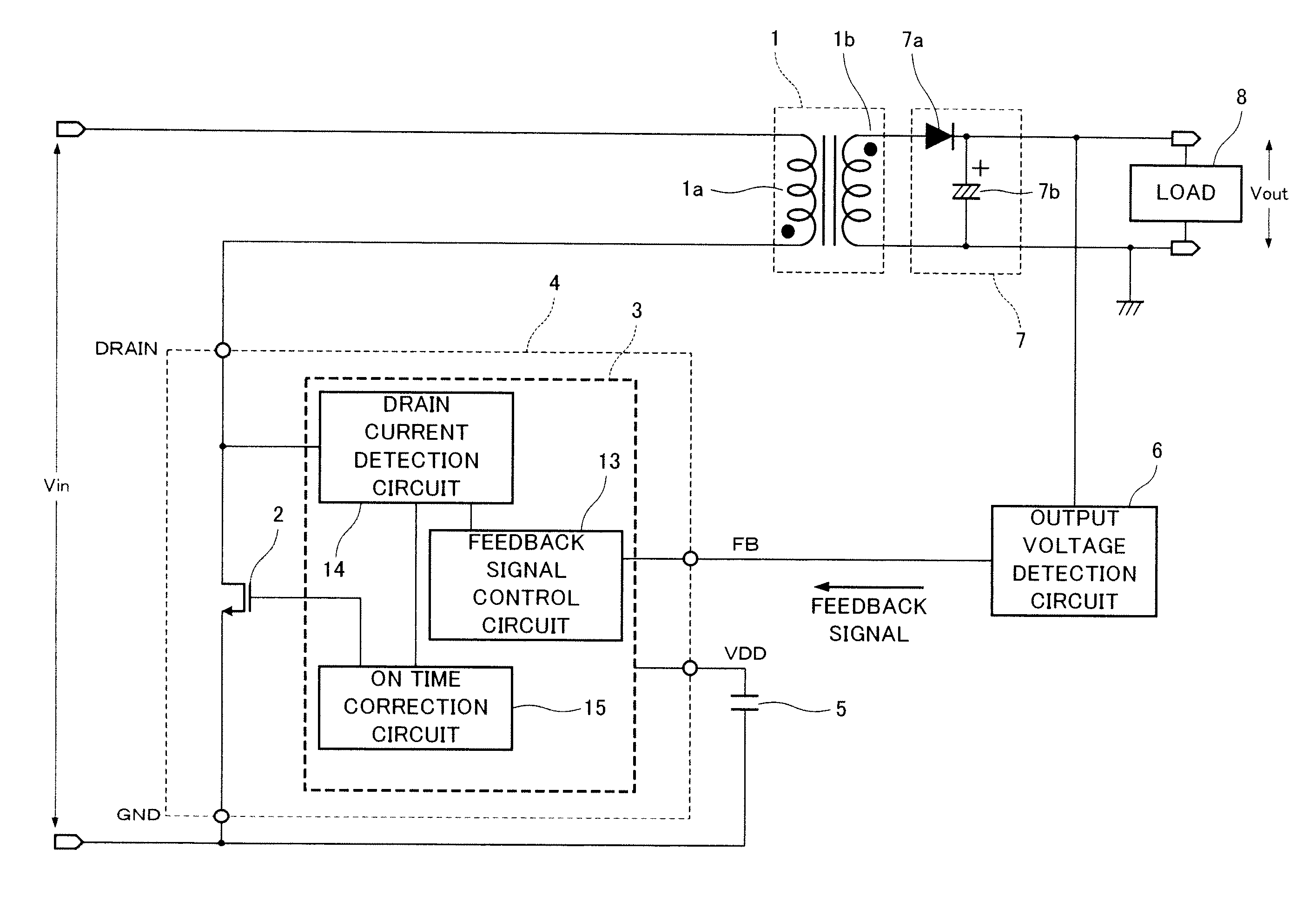
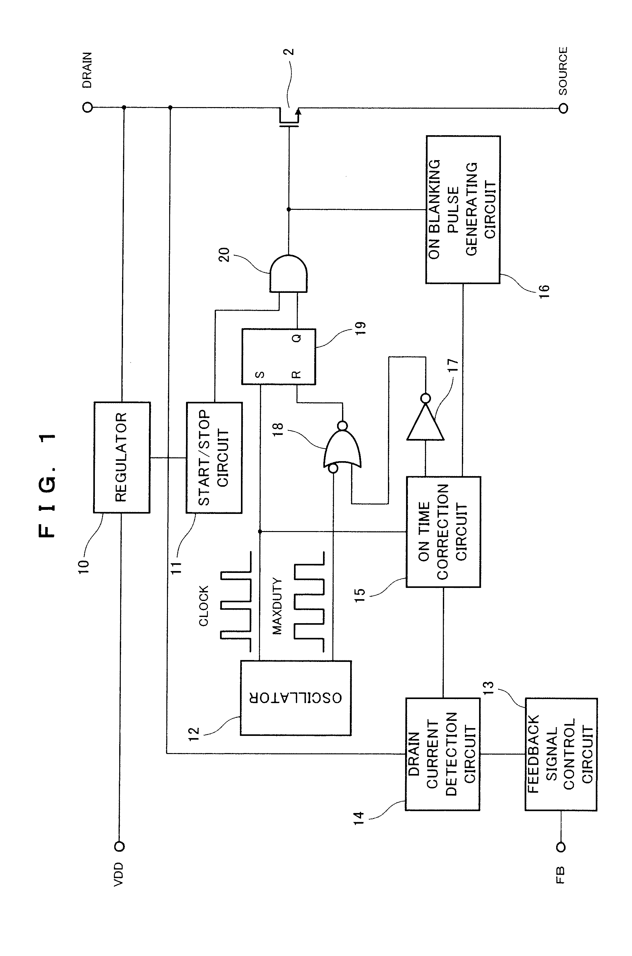
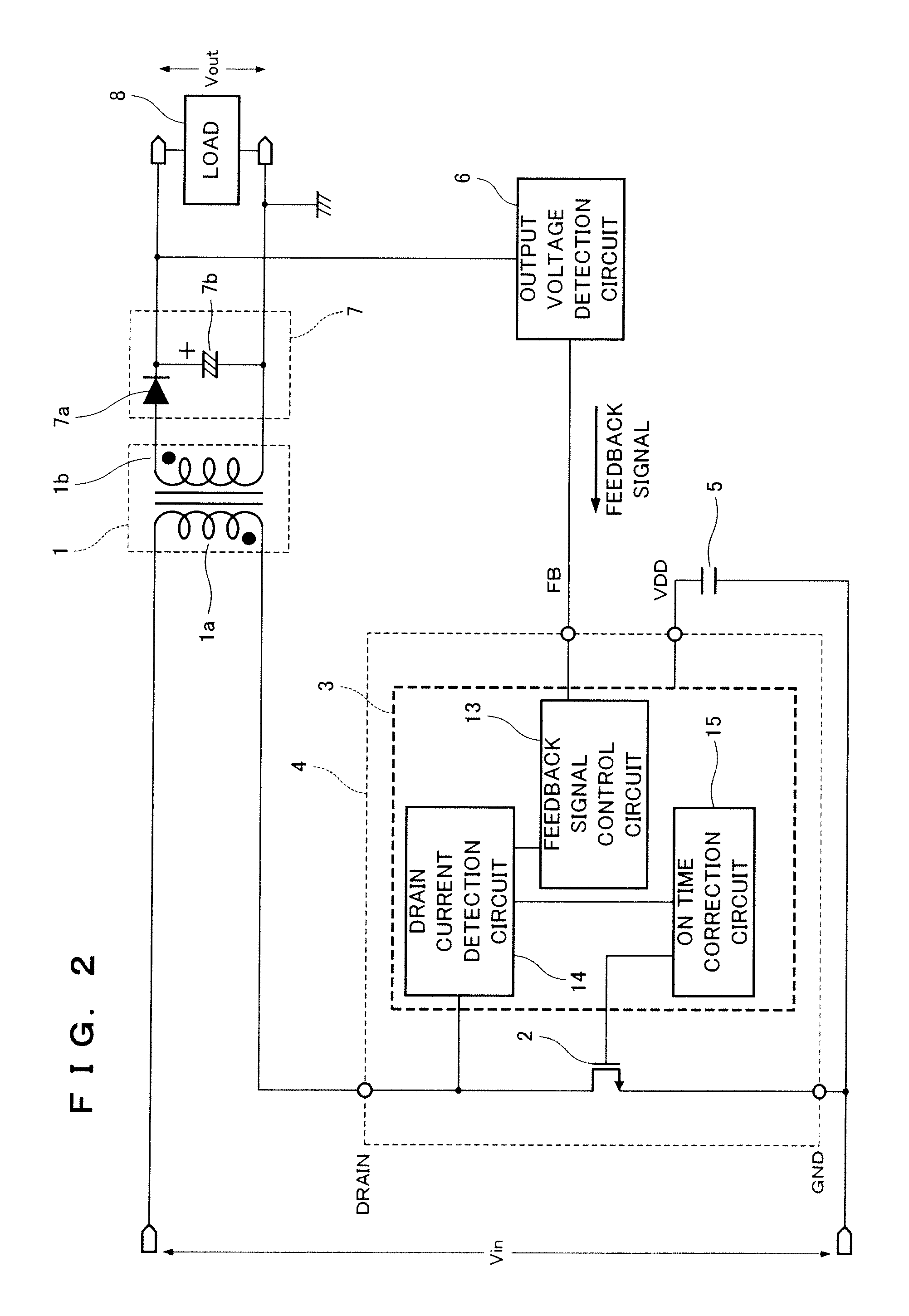
[0032]FIGS. 1, 2 and 4 are circuit diagrams showing a structural example of the switching power supply controller according to the first embodiment.

[0033]In the switching power supply controller, a transformer 1 has a primary winding 1a and a secondary winding 1b, the transformer 1 acting as a converter for outputting an AC voltage obtained by converting the waveform of an input DC voltage Vin in response to the switching operation of a switching element 2. The primary winding 1a and the secondary winding 1b are opposite in polarity. The switching power supply controller is a flyback controller.

[0034]The switching element 2 is connected in series to the primary winding 1a. The control electrode of the switching element 2 undergoes on / off switching control in response to the output signal of a control circuit 3. Th...

second embodiment

[0066]The following will describe a switching power supply controller according to a second embodiment of the present invention and a semiconductor device used for the same.

[0067]FIG. 6 is a circuit diagram showing a structural diagram of an on time correction circuit 15 of the switching power supply controller according to the second embodiment and the semiconductor device used for the same. As compared with the first embodiment, the threshold value of an inverter circuit 35 changes with a change of a VDD voltage of the inverter circuit 35 and a tdoff time depends upon the VDD voltage. Thus in the second embodiment, the dependence of the on time correction circuit 15 on the VDD voltage is improved. The operational description is similar to that of the first embodiment and thus only different points will be discussed below.

[0068]In FIG. 6, reference numeral 24 denotes an RS flip-flop, reference numerals 26 and 27 denote constant current sources, reference numerals 28, 29 and 32 deno...

third embodiment

[0074]The following will describe a switching power supply controller according to a third embodiment of the present invention and a semiconductor device used for the same.

[0075]FIGS. 7 and 8 are circuit diagrams showing a structural example of a drain current detection circuit 41 of the switching power supply controller according to the third embodiment and the semiconductor device used for the same. As compared with the first embodiment, as shown in FIG. 8, reference numeral 42 denotes a resistor, reference numeral 43 denotes a reference voltage source, and reference numeral 44 denotes a comparator. In the drain current detection circuit 41, a voltage corresponding to a drain current is applied to the positive side of the comparator 44, the reference voltage source 43 is connected to the negative side of the comparator 44, and the output of the comparator 44 is connected to an AND circuit 20. To the positive side of the comparator 44, a lower voltage is inputted as compared with t...


PUM


Abstract

In the present invention, according to a time from when a switching element 2 is turned on to when the switching element 2 reaches a set overcurrent detection level, an on time correction circuit 15 changes a time from when the switching element 2 reaches the overcurrent detection level to when the switching element 2 is turned off. Thus it is possible to keep constant the peak value of drain current passing through the switching element 2, regardless of an input voltage Vin.

Description

FIELD OF THE INVENTION [0001]The present invention relates to a switching power supply controller which controls an output voltage by using a switching operation on a DC voltage and supplies the output voltage to a load, and a semiconductor device used for the same.BACKGROUND OF THE INVENTION [0002]In the prior art, in order to improve power efficiency in response to lower power consumption, switching power supply controllers have been widely used as the power supplies of home use equipment such as home electrical appliances. The switching power supply controllers have switching power supply control semiconductor devices which control (stabilize) output voltages by using the switching operations of semiconductors (switching elements such as a transistor).[0003]Such a switching power supply controller of the prior art is disclosed in, for example, Japanese Patent Laid-Open No. 2007-166810.[0004]As shown in FIG. 10, the switching power supply controller includes an oscillator 712 for ...

Claims


Application Information

Patent Timeline
IPC IPC(8): H02M3/335
CPCH02M3/33507
Inventor FUKUI, MINORUHACHIYA, YOSHIAKI
Owner PANASONIC CORP
Why Eureka
Try Eureka