Motor

a motor and electric technology, applied in the direction of magnetic circuit rotating parts, magnetic circuit shape/form/construction, transportation and packaging, etc., can solve the problems of reducing the power factor of conventional electric motors, limiting the changeable range of field magnetic fluxes, and increasing current amplitude, so as to reduce rotation speed and torque the effect of large, torque-enhancing

Active Publication Date: 2022-03-22
NASHIKI MASAYUKI
View PDF6 Cites 0 Cited by
  • Summary
  • Abstract
  • Description
  • Claims
  • Application Information

AI Technical Summary

Benefits of technology

[0014]A rotation speed vs. torque characteristic of a main-machine motor for electric vehicles requires two issues: one is a combination of a larger torque in lower rotation speeds and a higher power factor which are required when the vehicle climbs a steep slope road, the other is to gain a constant output characteristic by field weakening control in a higher rotation speed range. The present invention is directed to satisfy the two mutually-conflicting characteristics, make the motor and inverter more compact in size, and allow such motor and inverter to be manufactured in lower cost.Solution to the Problems
[0016]The present configuration makes it possible to provide a larger torque and a higher power factor to the motor and a field weakening characteristic which can be provided by reduced current. Namely, the foregoing two mutually-conflicting characteristics can be satisfied at the same time.
[0018]With this configuration, the mutually-conflicting relationship between a larger torque with a higher power factor and a field weakening characteristic can be overcome. In addition to this advantage, the permanent magnet and the non-magnetic member can be arranged positionally effectively, so that it is possible to provide the motor with a higher motor characteristic.
[0020]The object of the present invention is to provide a main-machine motor, which is mounted in an electric vehicle, with i) a larger torque characteristic in lower rotation speeds needed when the vehicle climbs up a sloping road, while the larger torque characteristic is still maintained at a higher power factor, and ii) a field weakening control needed in higher rotation speeds, which can be performed effectively. The present invention provides advantages, one of which is realization of larger torque with a higher power factor, which results from cancelling a motor armature reaction using the magnetic characteristic of permanent magnets; another of which suppresses the permanent magnets from producing field magnetic fluxes excessively, which is resultant from a positionally effective arrangement of the non-magnetic member portions, such as resin materials or empty spaces; and another of which is realization of field weakening control which can be performed efficiently, As a result, the motor can be highly efficient, more compact in size, less in weight, and less in manufacturing cost. Additionally, the higher power factor can be led to reducing a current capacity needed by an inverter for driving the motor, thereby making the inverter more compact in size and lowering manufacturing cost of the inverter.

Problems solved by technology

However, the field magnetic fluxes have a limitation in a changeable range of the field magnetic fluxes.
However, this conventional electric motor has been confronted with a difficulty that the power factor is reduced, in a case where a larger amount of torque, which is more than three times the constant rating torque, is required for claiming a steep slope, and is required to output larger amounts of stator currents which generate larger armature reaction.
A reduction in the power factor results in larger current amplitudes, due to generation which is proportional to the inverse of the power factor, and an amount of copper loss increases, due to generation which is proportional to the square of current amplitudes
This results in supplying field weakening current components, but such field weakening current components increase the copper loss.
Any of the foregoing issues result in raising heat generated from the motor, thus tending to an increase of size of the motor to suppress influence of the generated heat.
However, this countermeasure can improve the torque characteristic, but the field weakening characteristic cannot be avoided from being deteriorated.
In this way, the higher torque and power factor and the field weakening characteristic in the range of higher rotation speeds becomes conflicting to each other, and it is thus difficult to provide higher levels of both factors at the same time.
In addition, there is another drawback that the local magnetic fluxes have larger torque ripples, due to the fact that the local magnetic flux has a distribution which is not a sinusoidal-wave cycle of an electric angle of 360 degrees and contains more harmonic components.

Method used


Image

  • Motor
  • Motor
  • Motor

Examples


Embodiment Construction

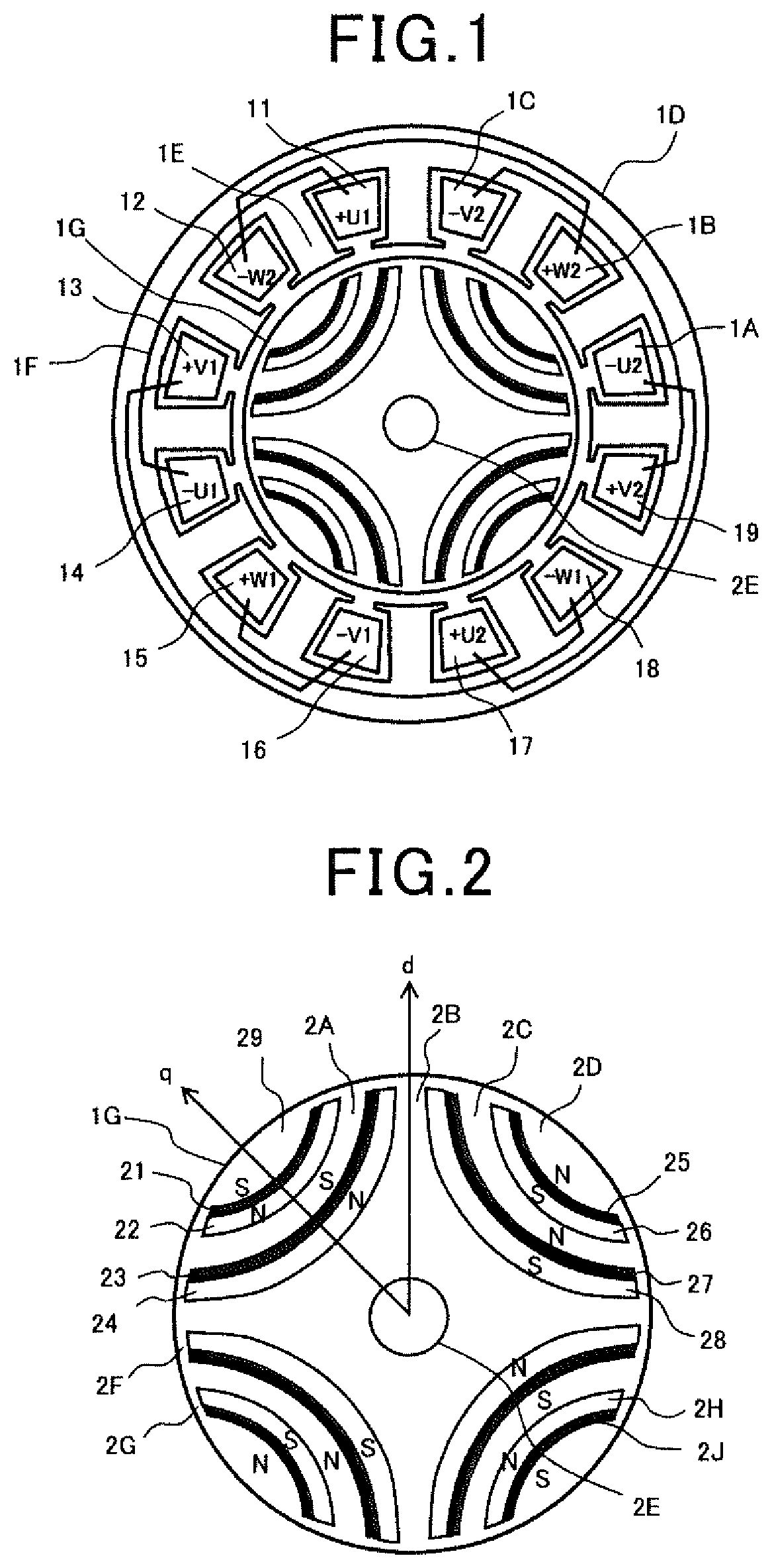
[0037]FIG. 1 is a sectional view showing an electric motor according to the present invention. The motor is a three-phase alternating current motor with four poles and 12 slots in windings that are wound in a full-pitch winding. This example shows a concentrated winging structure in which the wire for each of the phases is concentrated-wound in respective ones of the slots. A reference number 1D shows a stator, and reference numbers 11 and 14, 17 and 1A are U-phase windings. A U1 winding is wound to pass through designated slots as the windings 11 and 14, while a U2 winding is wound to pass through designated slots as the windings 17 and 1A. A connection wire 1F connects the windings in the slots in a coil end portion and other connection wires also connect the corresponding windings in the slots in the coil end portion. The reference numbers 13 and 16, 19 and 1C are windings for the V-phase, in which a V1 winding is wound to pass through designated slots as the windings 13 and 16, ...


PUM

PropertyMeasurementUnit
electric angleaaaaaaaaaa
current directionsaaaaaaaaaa

Abstract

A motor is provided, which has a larger torque and a high power factor in lower rotation speeds and a high power factor and a field weakened characteristic in a higher rotation speed range. The motor is provided with a long-hole shaped slit arranged between a rotor magnetic pole and a further rotor magnetic pole located adjacently to the rotor magnetic pole in a circumferential direction, a permanent magnet arranged in the slit, and a non-magnetic member arranged closely to the permanent magnet in a direction of magnetic fluxes. For large torque, this configuration reduces variations in rotor field magnetic fluxes, due to torque current components. In the rotation speeds, magnetic fluxes from the permanent magnet is suppressed from causing excessive field magnetic fluxes, which balances larger torque with higher power factors and a field weakened characteristic with higher power factors.

Description

CROSS-REFERENCE TO RELATED APPLICATIONS[0001]This application is based on and claims the benefit of priority from earlier PCT international application number PCT / JP2017 / 016026 filed on Apr. 21, 2017, which is also based on Japanese Patent Application No. 2016-086704 filed on Apr. 25, 2016, the descriptions of which are incorporated herein by reference.BACKGROUNDTechnical Field[0002]The present disclosure relates to electric motors for main machines, industrial motors, and driving techniques therefor, and particularly, relates to providing a motor system with higher efficiency, downsized structure, and / or lowered-cost production.Related Art[0003]Interior Permanent Magnet motors are used as motors serving as main machines for hybrid vehicles and industrial motors. It is estimated that when electric vehicles become common more widely in the future, needs for providing main-machine motors with higher performance, more downsizing, and lower cost will be asked more. Concerning an inverte...

Claims


Application Information

Patent Timeline
Patent Type & Authority Patents(United States)
IPC IPC(8): H02K1/27H02K1/276H02K21/16
CPCH02K1/276H02K1/27H02K21/16Y02T10/64
Inventor NASHIKI, MASAYUKI
Owner NASHIKI MASAYUKI
Why Eureka
Try Eureka