Apparatus and method for locking a tire vulcanizing press

Inactive Publication Date: 2004-02-19
COLE JOHN R
View PDF17 Cites 20 Cited by
  • Summary
  • Abstract
  • Description
  • Claims
  • Application Information

AI Technical Summary

Benefits of technology

0026] It is yet another object of the present invention to provide a tire press that is more co

Problems solved by technology

This results in an uneven load distribution which results in uneven strains and stresses.
This may eventually cause tire defects because upper and lower tire molds may no longer be parallel.
Further, the lock rods need to be over designed to take into consideration the fact that some of t

Method used


Image

  • Apparatus and method for locking a tire vulcanizing press
  • Apparatus and method for locking a tire vulcanizing press
  • Apparatus and method for locking a tire vulcanizing press

Examples


Embodiment Construction

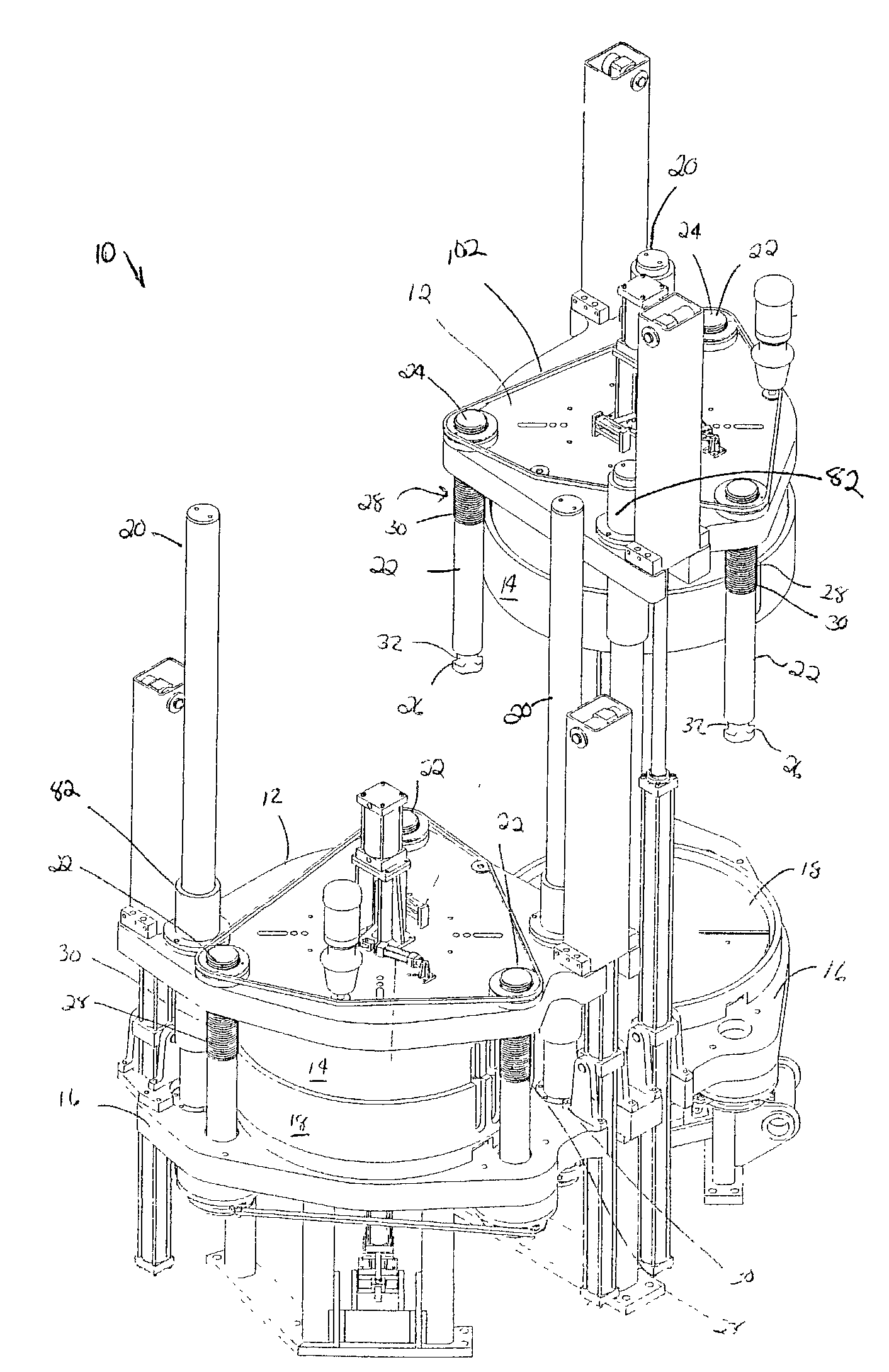
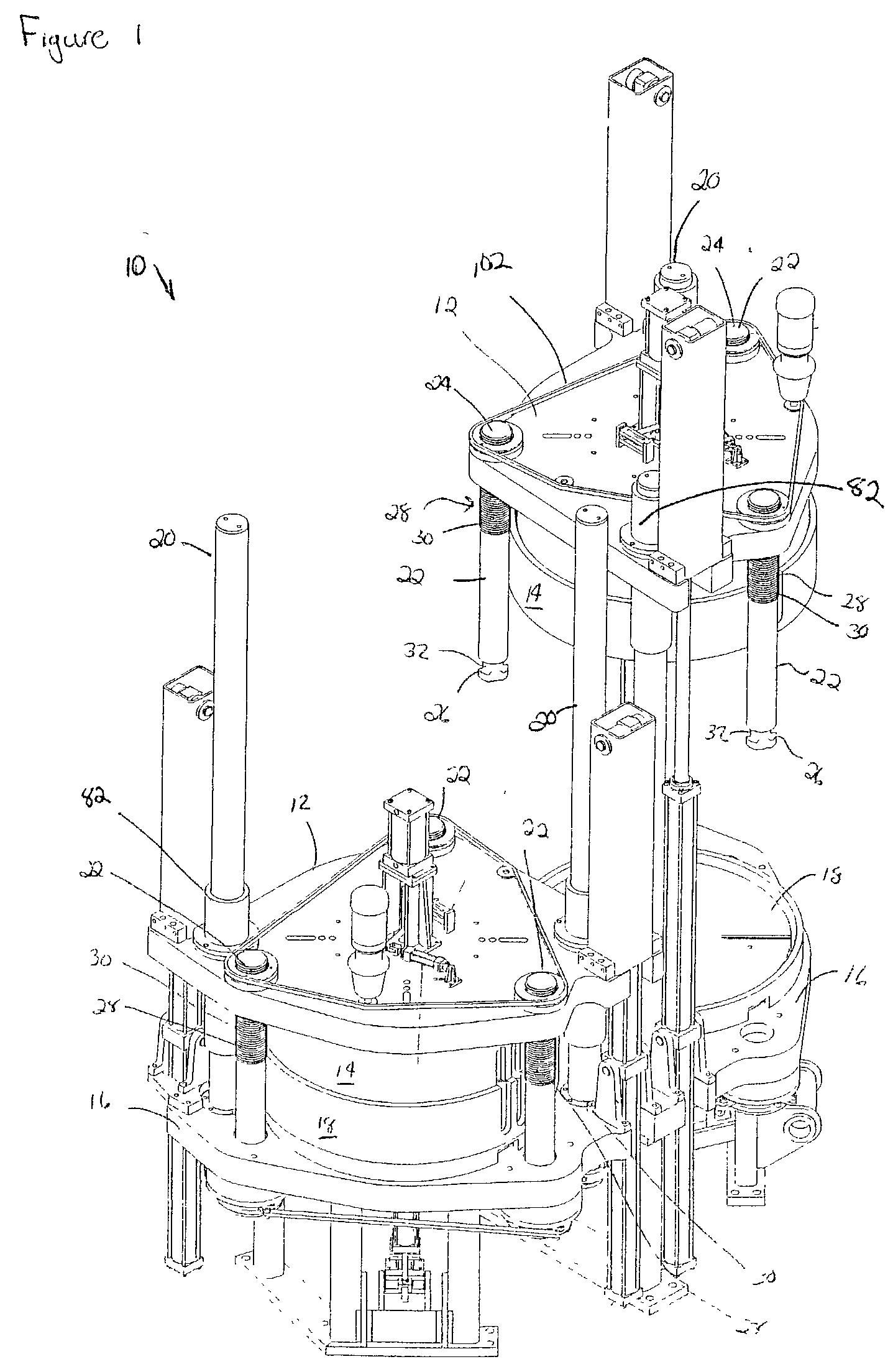
[0034] Referring now to the drawings wherein the showings are for purposes of illustrating a preferred embodiment of the invention only and not for purposes of limiting the same, FIGS. 1-5 show the present invention.

[0035] With reference to FIGS. 1-4 a tire press 10 is shown. A tire press 10 may take the form of two single cavity machines that work independently. The tire press comprises a top plate 12 having an upper mold 14 rigidly affixed thereto. A bottom mold 18 is fixedly attached to the bottom plate 16. The bottom mold 18 and upper mold 14 contact each other and maintain alignment through a plurality of guide rods 20.

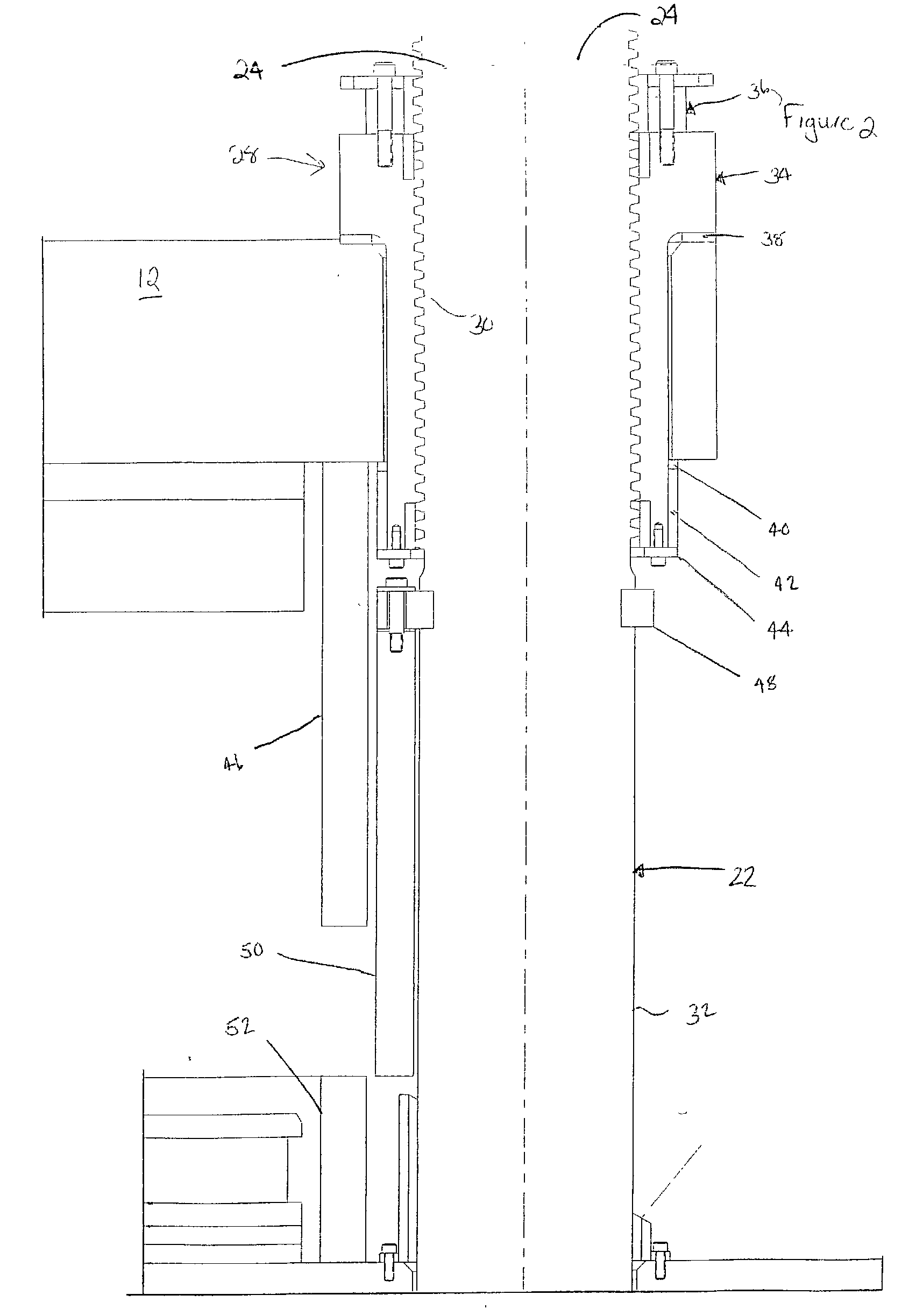
[0036] The tire press 10 further comprises a plurality of lock rods 22, which passes through the top plate 12. Each of the lock rods has a first end 24, a second end 26, and a surface 32. The second end 26 may be notched. The purpose of the lock rods 22 is to maintain tight and even seal between the upper mold 14 and bottom mold 18 during a curing cycle. It is im...


PUM

PropertyMeasurementUnit
Heightaaaaaaaaaa
Tensionaaaaaaaaaa

Abstract

A tire press has an upper mold fixedly attached to a top plate. A bottom mold is fixedly attached to a bottom plate. The tire press has a plurality of guide posts adapted to maintain proper alignment of the upper mold and the lower mold as the tire press opens and closes. A plurality of lock rods, which are independent of the guide posts, are positioned about the tire press. Each of the lock rods has a first end and a second end. The lock rods may have an adjustment mechanism positioned on the first end of the lock rods to adjust the various mold heights. Locking means are a part of the tire press, which are adapted to selectively engage the second end of the lock rods. Further, each of the lock rods has cylinder mechanism operatively connected to the locking means. The cylinder mechanism is adapted to force the locking means to the surface of the lock rods. The cylinder mechanism is a hydraulic cylinder having the piston disposed within the chamber. The piston has a release side and a squeeze side, such that when fluid is introduced on the squeeze side, a substantially equal amount of tension is placed on the lock rods to lock the tire press. When fluid is introduced on the release side, the locking means can be removed from the lock rods and the tire press can be opened.

Description

1. BACKGROUND OF THE INVENTION[0001] A. Field of Invention[0002] This invention pertains to the art of methods and apparatuses for locking a tire press. More specifically, the present invention pertains to the art of methods and apparatuses for locking a tire press wherein a cylinder mechanism is utilized to provide substantially equal tension in all locking rods such that the tolerances for the length of each of the lock rods is not as critical as in known locking devices.[0003] B. Description of the Related Art[0004] It is known in the art for tire presses to have a locking mechanism so that a tire mold is secure during a curing cycle. Current devices utilize lock rods which must be substantially identical in length. As such, the lengths must be very precise and is very critical. The dimension is very critical because when a tire press closes and locks, if any of the lock rods are slightly longer than another one, the shorter rod sees more forces and loads. This results in an unev...

Claims


Application Information

Patent Timeline
IPC IPC(8): B29C33/20B29C35/02B29C33/22B29D30/06B29K21/00B29K105/24B29L30/00
CPCB29D30/0601B29C33/202B29D30/0603B29D30/06B29C33/20
Inventor COLE, JOHN R.
Owner COLE JOHN R
Why Eureka
Try Eureka