Vehicle Seat

a seat and seat technology, applied in the field of seat bases, can solve the problems of increasing the weight of the seat, increasing the complexity of the manufacturing process, and thus costing the manufacturing process, and achieve the effects of less weight, less block height, and compact siz

Active Publication Date: 2019-06-20
GORDON MURRAY TECH LTD
View PDF0 Cites 2 Cited by
  • Summary
  • Abstract
  • Description
  • Claims
  • Application Information

AI Technical Summary

Benefits of technology

[0016]The seat base may comprise a sliding mechanism mounted between the side plates and the vehicle for selectively sliding the seat base forwards or backwards relative to the vehicle, as is well-known. There will also be additional structure to the vehicle seat, including a seat back, and this will be described with reference to the drawings. It will be appreciated that a vehicle seat base in accordance with the invention allows vehicles and vehicle seats to be manufactured which have significant advantages over conventional designs, including lower block height, more compact size and lighter weight yet equal or superior strength characteristics, and which are relatively easy and inexpensive to manufacture and to recycle at the end of their life. Such advantages are desirable and / or appropriate in the context of small urban automotive vehicles, but are equally as applicable in any other contexts where these advantages might be beneficial, such as in other forms of vehicle as trucks, buses and aircraft, for example.

Problems solved by technology

However, compared to bonding, there are significant disadvantages to this solution in that it adds weight to the seat and considerable complexity and thus cost to the manufacturing process.

Method used


Image

  • Vehicle Seat
  • Vehicle Seat
  • Vehicle Seat

Examples


Embodiment Construction

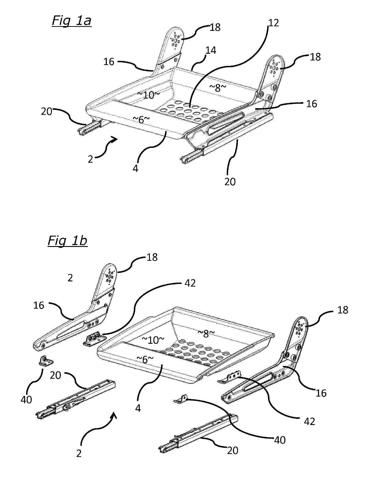
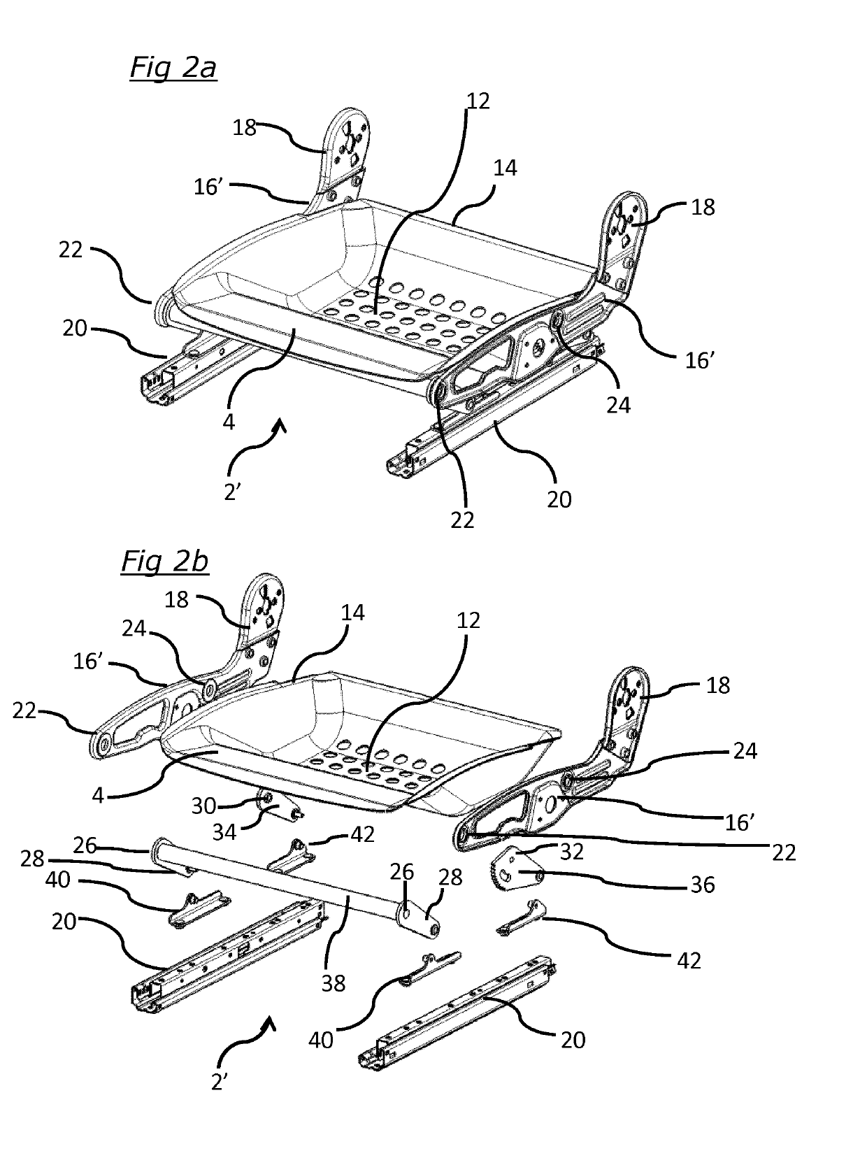
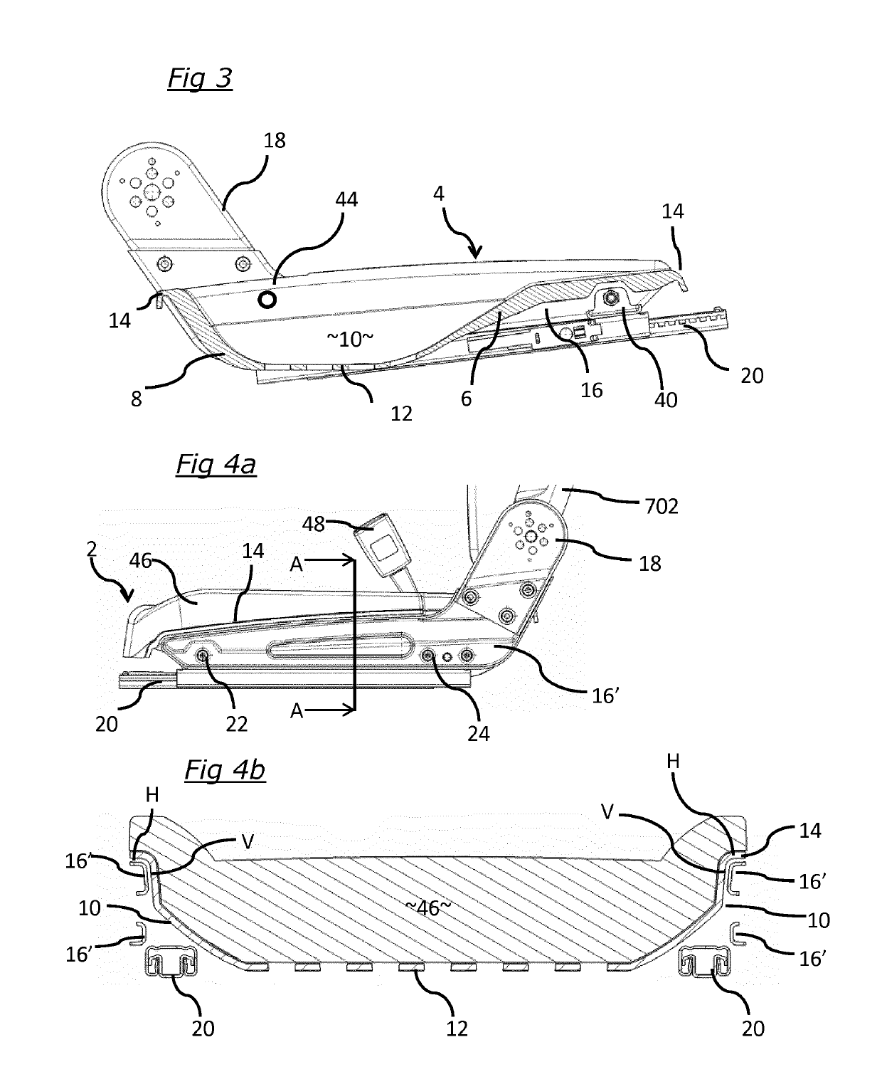
[0030]In the drawings, elements with like reference numerals are generally the same; where an element having the same general function has been modified for some reason, the reference numeral will gain a suffix in the form of an apostrophe. Where an element is intended somehow to complement another element its reference numeral will gain a suffix in the form of an additional letter.

[0031]FIGS. 1a and 1b show a seat base 2 in accordance with the invention (but without the usual padding, cushioning, upholstery, trim etc. which would be present in a finished seat) which comprises a concave seat pan 4 formed in a single, unitary piece of composite material. The seat pan 4 is defined by generally downwardly extending faces or sections at the front 6, at the rear 8 and at the lateral sides 10, and a generally horizontal bottom face or section 12. The upper edges of the front, rear and side faces 6, 8, 10 define a circumferential lip 14 of the seat pan 4. To the sides of the seat pan 4 are...


PUM


Abstract

A vehicle seat having a vehicle seat base comprising a generally concave seat pan (4) and side plates (16) fixed to the seat pan for mounting the seat pan to the vehicle wherein the seat pan has, all relative to the direction of movement of the vehicle, a front face, a rear face, two lateral side faces and a bottom face, and wherein the side plates extend from the front towards the rear of the seat pan and are bonded to the lateral side faces along at least part of the length of each of the side plates. This produces a lightweight yet rigid seat base which enables a low block height.

Description

FIELD OF THE INVENTION[0001]The present invention relates to a seat base for a vehicle seat, particularly but not exclusively for a compact city car or sports car.BACKGROUND ART[0002]Some form of seating is essential for the driver and passengers in a car or other vehicle, to support them in comfort during the journey and restrain them in the event of a collision. There are many different designs for vehicle seats, but they generally consist of a seat base with a seat back mounted thereto. The seat base supports the buttocks and thighs of a person occupying the seat, and the seat back supports the person's back, from the buttocks to the shoulders, or to the back of the head. The seat back can be fixedly mounted to the seat base, in a generally upright position, or it may be pivotally mounted to the seat base, so as to be movable between an upright position and a less upright, or reclined, position. In vehicle seat design and especially automotive seat design, there are often quite d...

Claims


Application Information

Patent Timeline
Patent Type & Authority Applications(United States)
IPC IPC(8): B60N2/68
CPCB60N2/686B60N2/0705B60N2/1615B60N2/643B60N2/646B60N2/68B60N2/682B60N2/0732B60N2/2222B60N2/16B60N2/0735B60N2/06
Inventor CLARK, STUART EDWARDSMITH, ANDREW JOHN
Owner GORDON MURRAY TECH LTD
Why Eureka
Try Eureka