Portable hemming apparatus and method

a hemming device and portable technology, applied in metal working devices, metal-working apparatuses, manufacturing tools, etc., can solve the problems of large hemming devices, difficult to move, and fail to solve, and achieve the effect of compact siz

Inactive Publication Date: 2006-03-16
HIROTEC AMERICA
View PDF2 Cites 2 Cited by
  • Summary
  • Abstract
  • Description
  • Claims
  • Application Information

AI Technical Summary

Benefits of technology

[0004] The present invention provides a portable hemming apparatus for performing both hemming and pre-hemming of metal panels on a final assembly line or a pre-assembly work cell. The hemming apparatus has the advantage of being more compact in size, lightweight, and portable than other similar apparatus. Thus, the present hemming apparatus can be transported to metal panels by mounting it to a robot, hanging it from a manually operated tool balancer, or integrating it into other tooling to act as a secondary operation. The portability of the hemming apparatus allows it to be integrated into a final assembly line or a pre-assembly work cell. Alternatively, the hemming apparatus can be mounted on a pedestal stand or other similar structure if it is instead desired to transport metal panels to the apparatus.

Problems solved by technology

This is undesirable because it is difficult to interchange hemming devices to hem different types of metal panels and because the panels must be moved directly into the hemming device.
This is an improvement over the conventional method, but still fails to solve the problem that hemming devices are large, heavy, difficult to move, difficult to change with regards to the hemming die, and expensive to produce and maintain.

Method used


Image

  • Portable hemming apparatus and method
  • Portable hemming apparatus and method
  • Portable hemming apparatus and method

Examples


Embodiment Construction

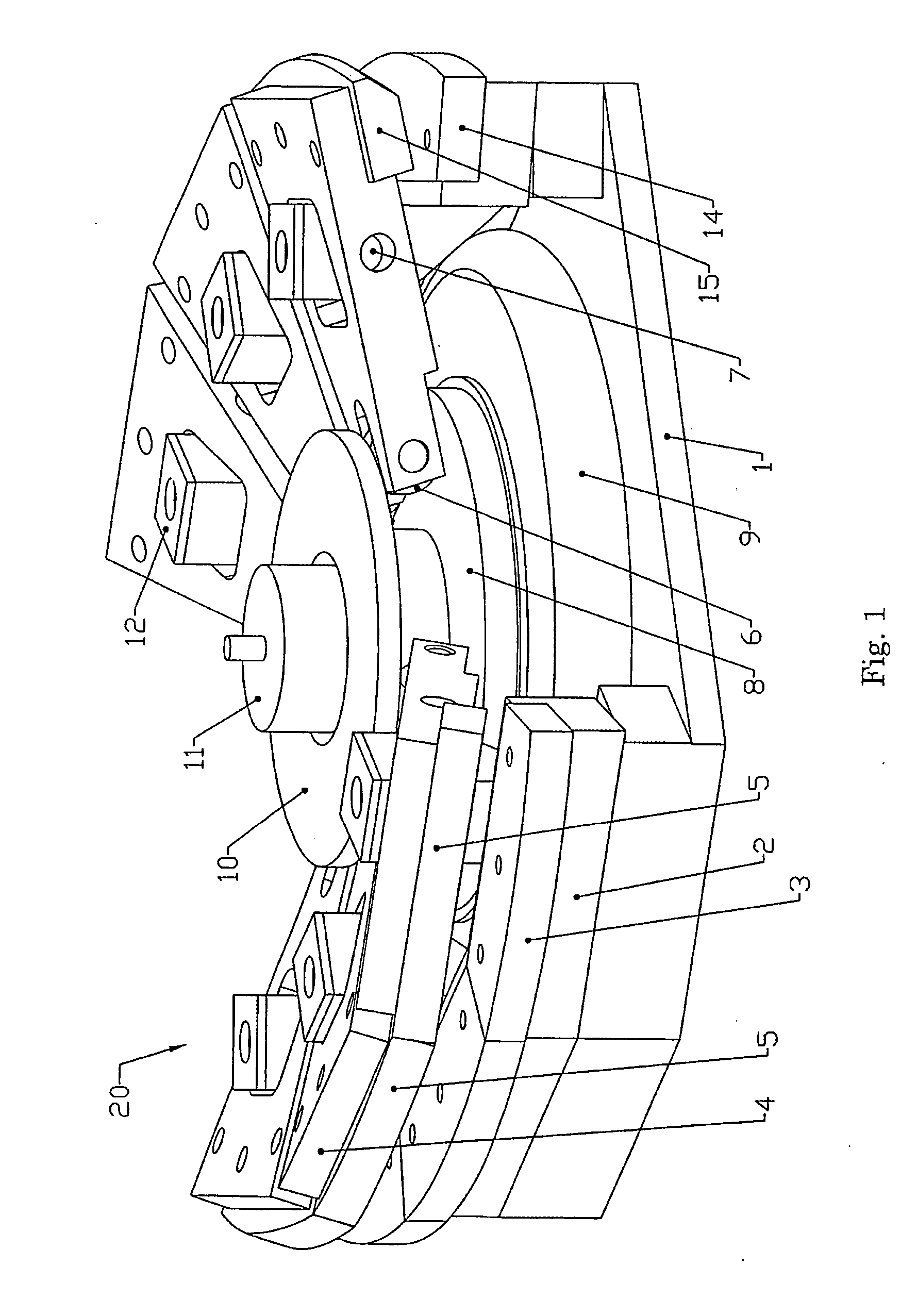
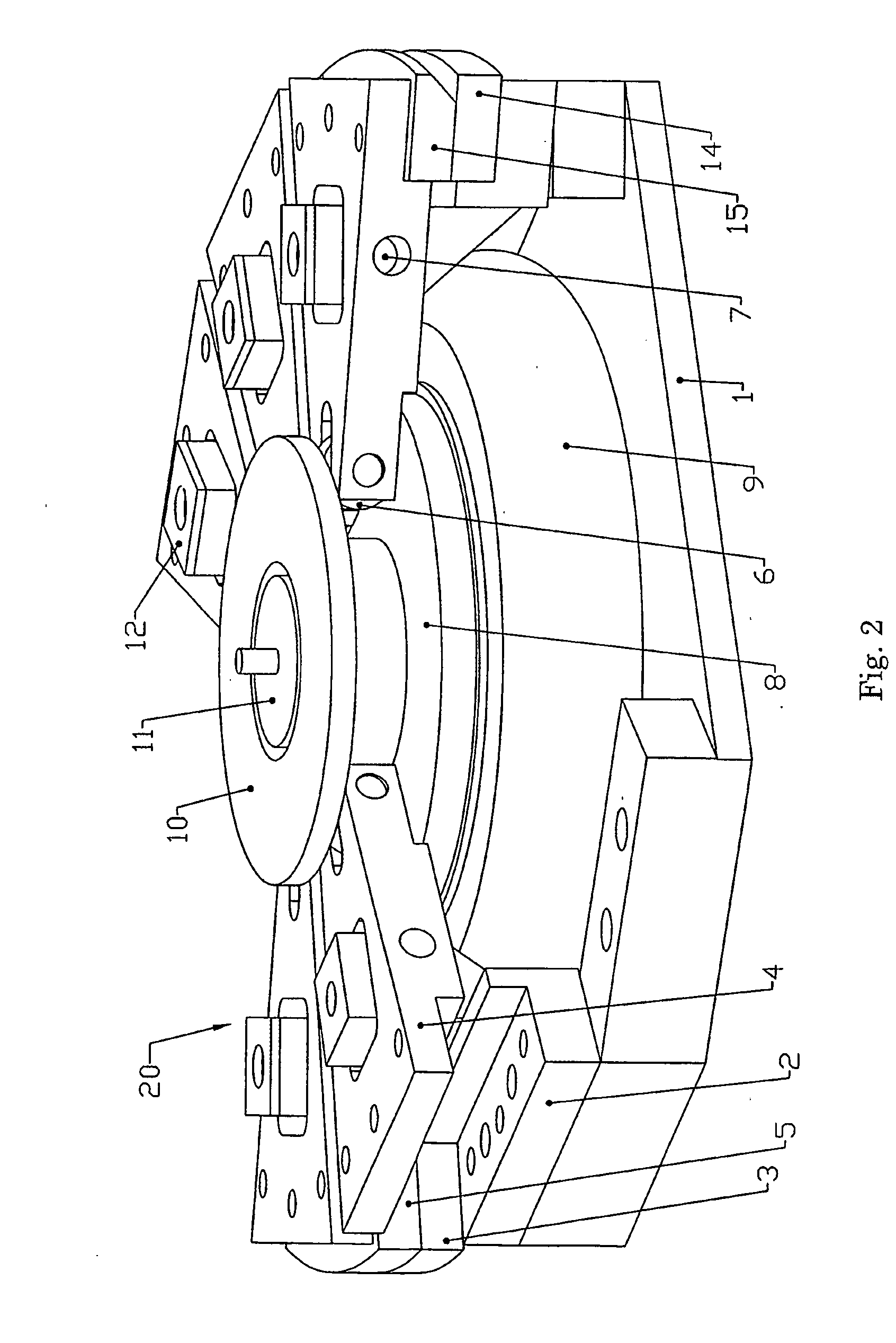
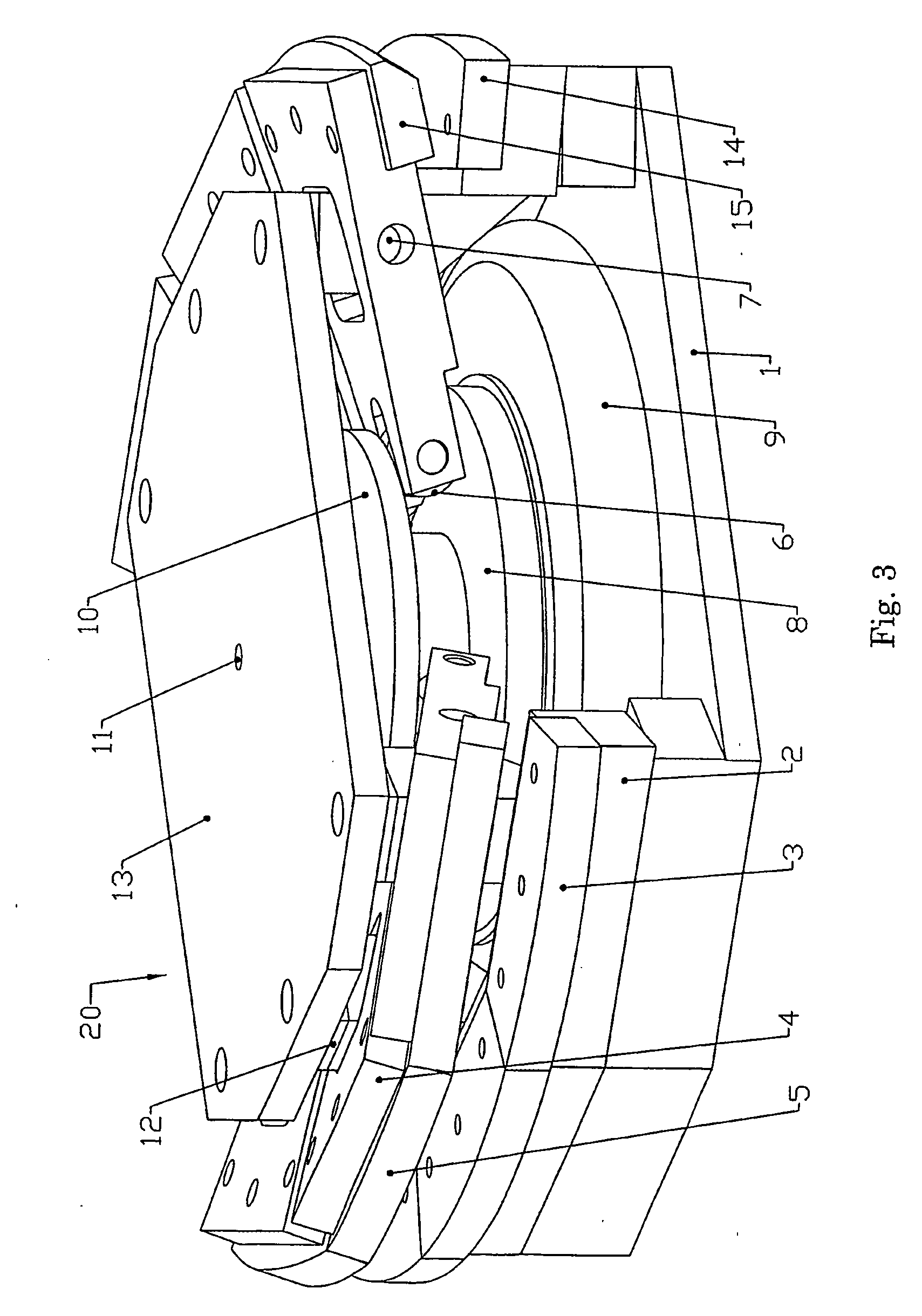
[0026] Referring now to the drawings in detail, numeral 20 generally indicates a portable hemming apparatus comprising a support structure 1, a plurality of modular hem die holders 2 attached to the support structure 1, and a corresponding plurality of hem punches 5, 15. A corresponding plurality of hem dies 3, 14 is mounted to the hem die holders 2. The hem punches 5, 15 are operatively connected to lever arms 4 which can freely rotate about pivots 7 mounted in the hem die holders 2. Moveable engagement members 6 fixed in the lever arms 4 rest on a roller plate 8, such roller plate 8 being attached to a first air spring drive 9. The first air spring drive 9 is connected to the support structure 1 on the side opposite the roller plate 8.

[0027]FIGS. 1 and 3 show the hemming apparatus 20 in a retracted position while FIG. 2 shows the hemming apparatus 20 in an extended hemming position. The hemming apparatus 20 is at rest in the retracted position. When fluid power is applied to the ...


PUM

PropertyMeasurementUnit
distanceaaaaaaaaaa
sizeaaaaaaaaaa
flexibilityaaaaaaaaaa

Abstract

A portable hemming apparatus includes a support structure, a plurality of modular self-contained hemmers disposed about the support structure and at least one pneumatic drive mounted on the support structure. Each modular hemmer includes a hem die holder, a hem die fixed to the hem die holder and a movable hem punch. A hem operator is operatively connected to each modular hemmer. Each hem operator is a lever arm assembly. Actuation of the drive moves the hem operators and causes the hem punches to close and open on the hem die, allowing for the hemming of a metal panel located within the modular hemmers. The support structure of die hemming apparatus can be adapted to be mounted on a robot arm, mounted on a pedestal stand, or hung from a tool balancer. These arrangements allow for various uses of the hemming apparatus. Further, the modular design of the hemmers allows the apparatus to be used for the hemming of various sizes and shapes of panels.

Description

CROSS REFERENCE TO RELATED APPLICATION [0001] This application claims the priority of provisional application 60 / 392,016 filed Jun. 26, 2002.TECHNICAL FIELD [0002] This invention relates to the field of hemming one or more performed metal panels together to form a hemmed joint or closed panel, and more particularly to an improved apparatus and method for completing the hemming procedure. BACKGROUND OF THE INVENTION [0003] It is known in the art relating to hemming to use a conventional press structure as the hemming device. It is also known to transport the metal panels to be hemmed to the hemming device itself. This is undesirable because it is difficult to interchange hemming devices to hem different types of metal panels and because the panels must be moved directly into the hemming device. It is further a newly known method of hemming to recognize a set of metal panels (a “workpiece”) and to move a corresponding hemming die to the workpiece. This is an improvement over the conve...

Claims


Application Information

Patent Timeline
Patent Type & Authority Applications(United States)
IPC IPC(8): B21D39/00B21D39/02
CPCY10T29/49908B21D39/021
Inventor STEED, JAMESJTOENISKOETTER, JAMESB
Owner HIROTEC AMERICA
Why Eureka
Try Eureka