Tunable system and method for tuning a system

Active Publication Date: 2014-12-04
DSP GROUP
View PDF6 Cites 5 Cited by
  • Summary
  • Abstract
  • Description
  • Claims
  • Application Information

AI Technical Summary

Benefits of technology

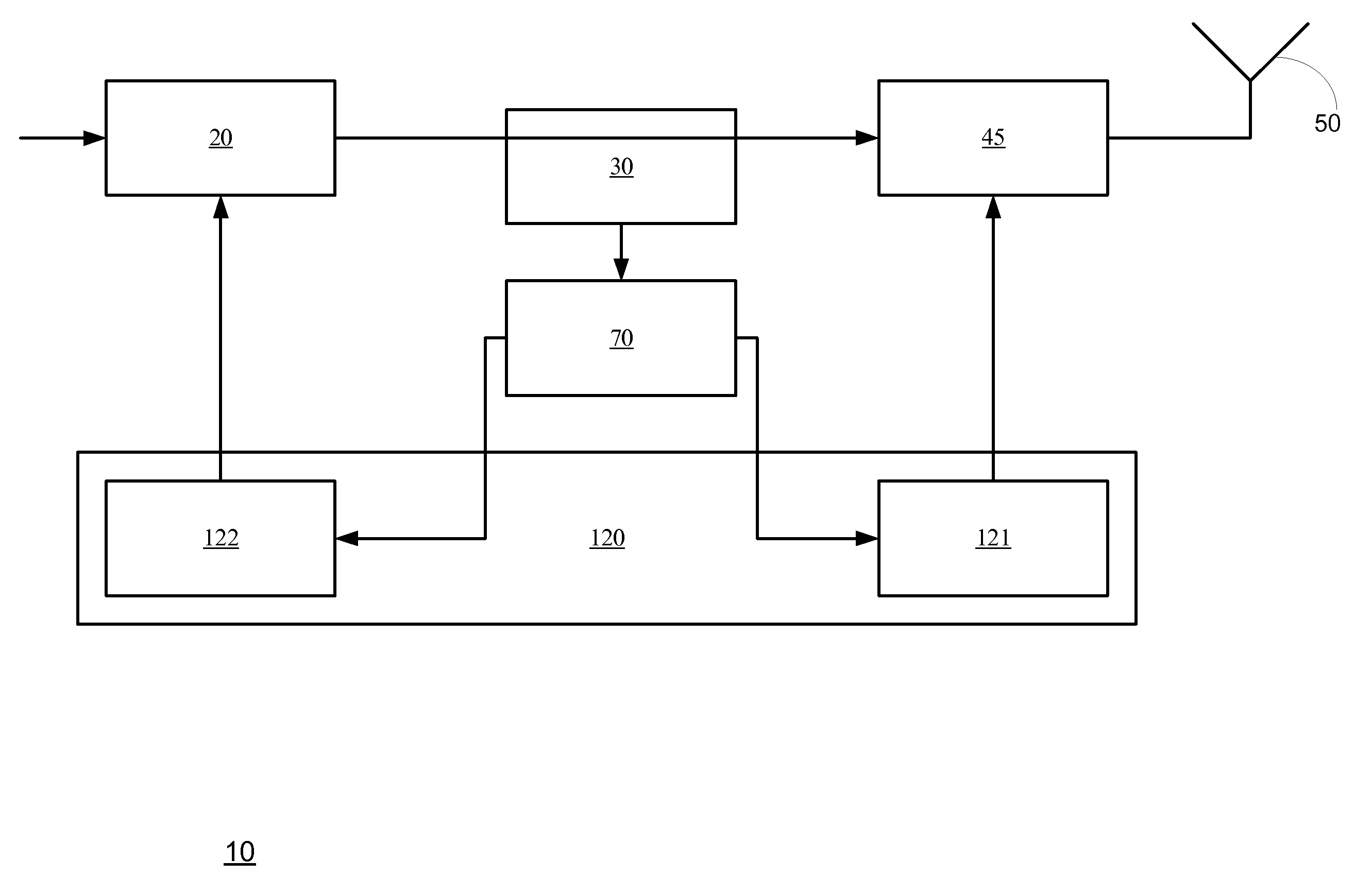
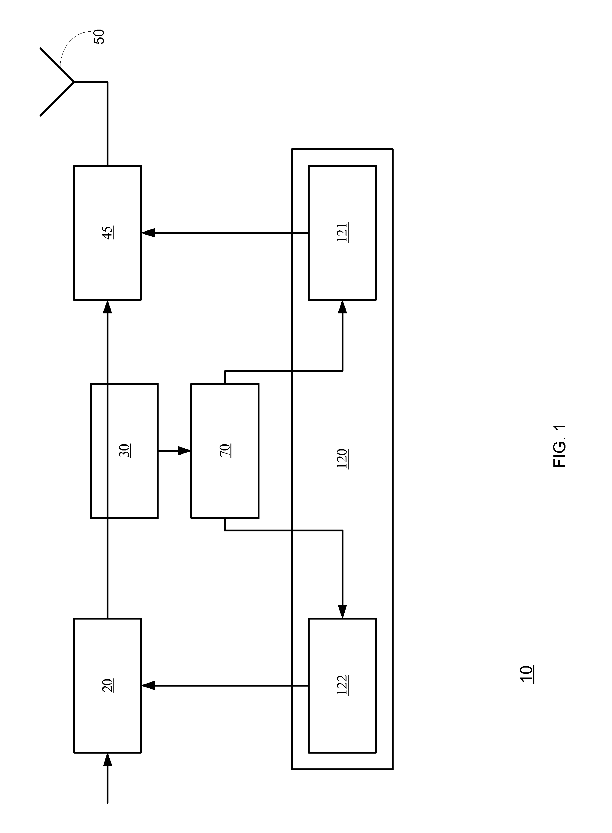
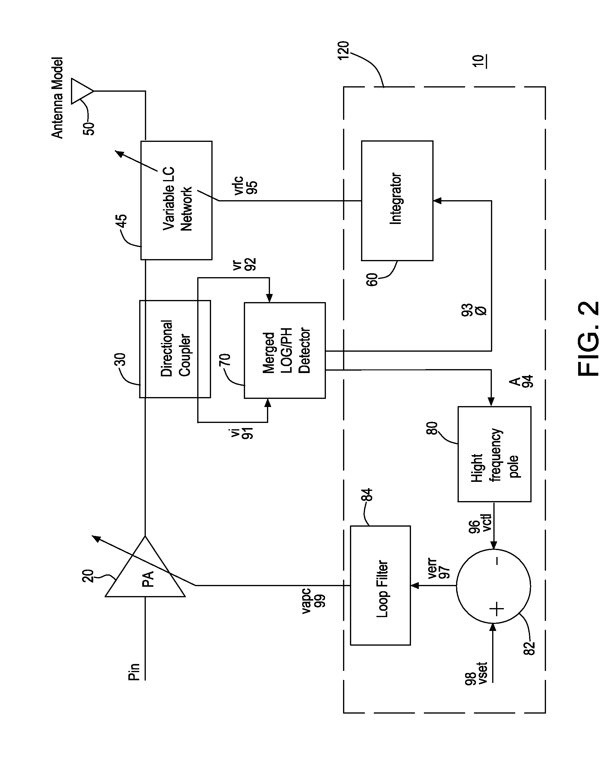
[0016]According to an embodiment of the invention there may be provided a system that may include a tunable amplification module that may be arranged to amplify an input signal for providing an incident signal; wherein the tunable amplification module has an output port for outputting the incident signal, an input port for receiving the input signal and a control input for receiving an amplification module tuning signal for tuning the amplification factor of the tunable amplification module; a coupler that may be arranged to output a first signal that represents the incident signal and a second signal that represents a reflected signal; an interface module; a detector that may be arranged to receive the first and second signals and to output an impedance indicative signal and a power indicative signal; wherein the impedance indicative signal is indicative of an impedance mismatch between an output impedance of the tunable amplification module and a

Problems solved by technology

These sometime contradicting linearity and p

Method used


Image

  • Tunable system and method for tuning a system
  • Tunable system and method for tuning a system
  • Tunable system and method for tuning a system

Examples


Embodiment Construction

[0031]In the following detailed description, numerous specific details are set forth in order to provide a thorough understanding of the invention. However, it will be understood by those skilled in the art that the present invention may be practiced without these specific details. In other instances, well-known methods, procedures, and components have not been described in detail so as not to obscure the present invention.

[0032]In the following detailed description, numerous specific details are set forth in order to provide a thorough understanding of the invention. However, it will be understood by those skilled in the art that the present invention may be practiced without these specific details. In other instances, well-known methods, procedures, and components have not been described in detail so as not to obscure the present invention.

[0033]The subject matter regarded as the invention is particularly pointed out and distinctly claimed in the concluding portion of the specific...


PUM


Abstract

There is provided a system that includes a tunable amplification module, a coupler, an interface module; a detector that is arranged to output an impedance indicative signal and a power indicative signal; wherein the impedance indicative signal is indicative of an impedance mismatch between an output impedance of the tunable amplification module and an impedance of a radio frequency (RF) antenna as seen by the tunable amplification module, wherein the power indicative signal is indicative of an output power of the tunable amplification module.

Description

FIELD OF THE INVENTION[0001]The present invention relates to antenna impedance matching of radio frequency (RF) transmission systems.BACKGROUND OF THE INVENTION[0002]Systems that transmit RF signals usually include an amplifier, followed by some passive structures as filters and switches that is connected via a matching network to an RF antenna. The impedances of the RF antenna and the amplifier should be matched and usually about fifty Ohms in order to optimize the transmission of RF signals via the RF antenna and minimize the voltage standing wave ratio (VSWR) at the RF antenna.[0003]On the other hand the impedance of the amplifier should be optimized so that the amplifier maintains a constant output power at the highest possible power efficiency.[0004]These sometime contradicting linearity and power efficiency demands are hard to fulfill.[0005]There is a growing need to provide system and method for tuning in an efficient manner RF systems in order to maintain the delivered power...

Claims


Application Information

Patent Timeline
IPC IPC(8): H04B1/04
CPCH04B1/0458
Inventor SPIEGEL, SOLON JOSE
Owner DSP GROUP
Why Eureka
Try Eureka