Patch panel and strain relief bar assembly

a strain relief bar and plate plate technology, applied in the direction of electrical equipment, substation/switching arrangement details, coupling device connections, etc., can solve the problem that neither of these prior art patents discloses quick release brackets

Active Publication Date: 2008-07-29
PANDUIT
View PDF27 Cites 72 Cited by
  • Summary
  • Abstract
  • Description
  • Claims
  • Application Information

AI Technical Summary

Benefits of technology

[0004]It would be desirable to provide quick release brackets that allow a strain relief bar to be removed from a patch panel for easy moves, adds and changes.
[0005]It would also be desirable to provide quick release brackets that allow a strain relief bar to be removed from a patch panel without using tools.

Problems solved by technology

However, neither of these prior art patents disclose quick release brackets for removably securing a strain relief bar assembly to a patch panel.

Method used


Image

  • Patch panel and strain relief bar assembly
  • Patch panel and strain relief bar assembly
  • Patch panel and strain relief bar assembly

Examples


Embodiment Construction

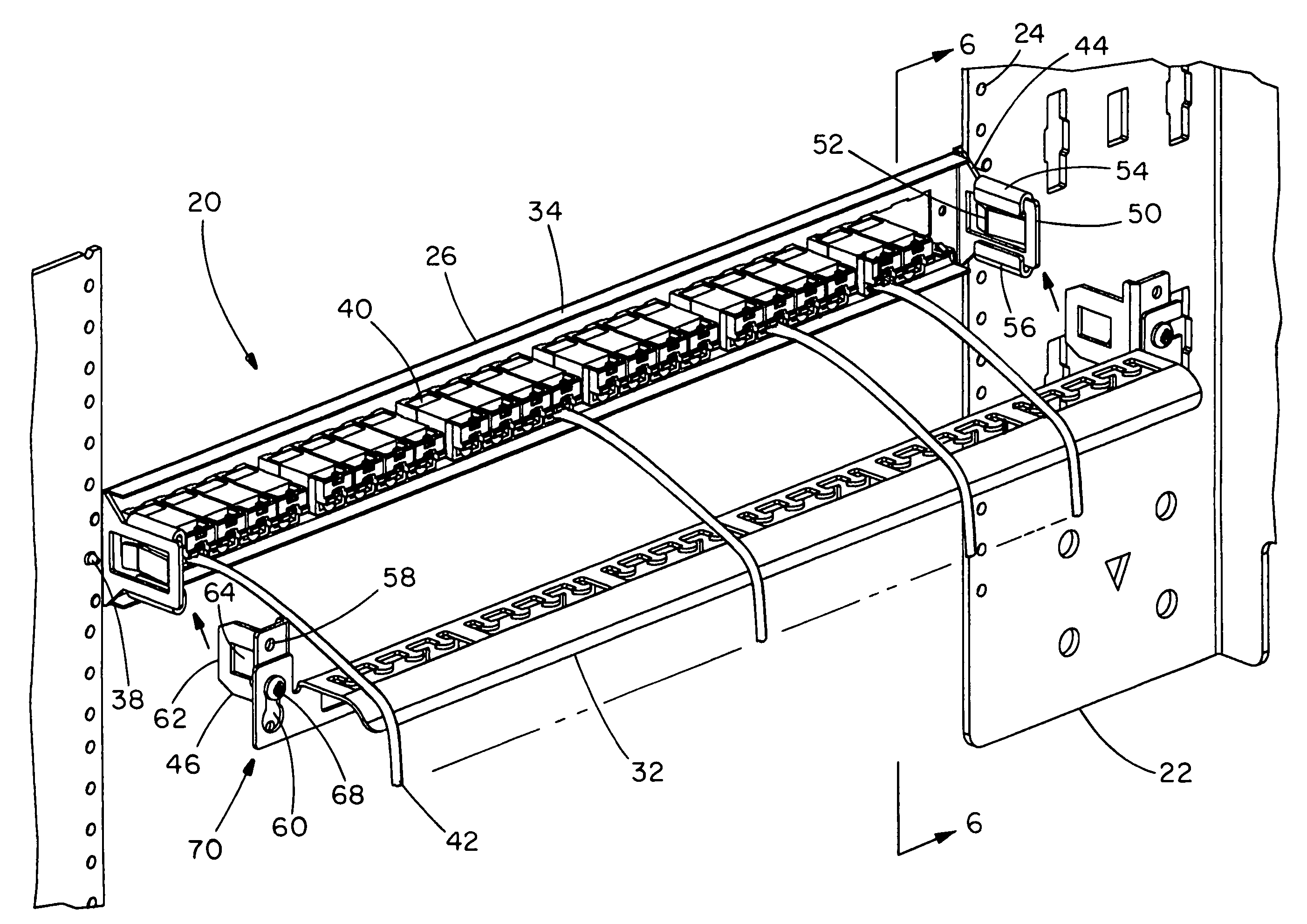
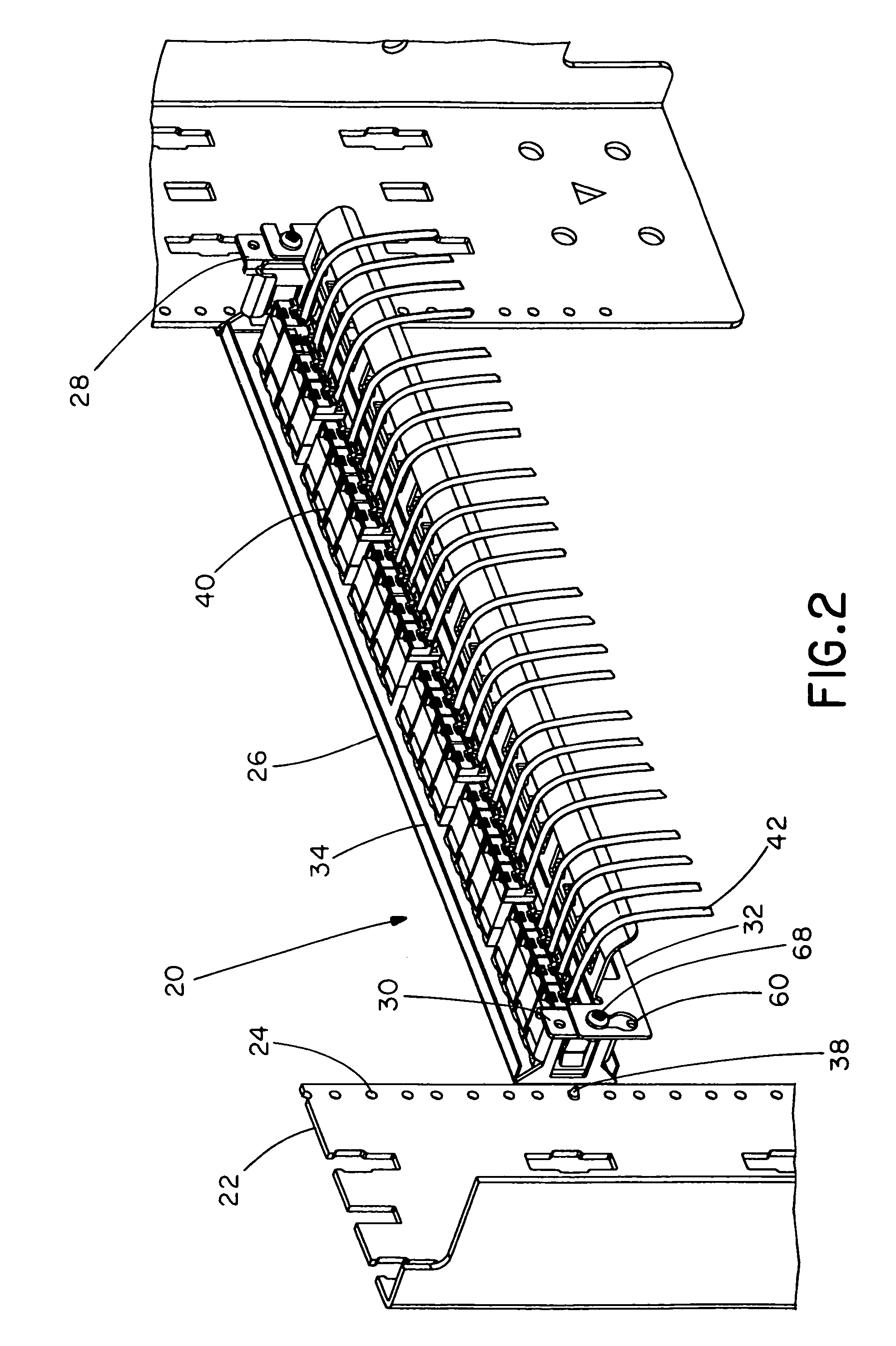
[0022]FIGS. 1-13 illustrate a patch panel and strain relief bar assembly 20 for use on either a rack cabinet or an open-frame rack, such as rack 22. As best seen in FIG. 1, rack 22 has equidistantly-spaced mounting holes 24 positioned vertically therealong. As shown in FIG. 3, assembly 20 includes patch panel 26, quick release brackets 28, 30 which attach to rack 22, and strain relief bar 32.

[0023]Patch panel 26 includes a frame 34 having mounting holes 36 at each end for securing patch panel 26 to the front side of rack 22 using screws 38. Frame 34 also includes connectors 40 having cable 42 exiting from the rear side thereof, as shown in FIG. 2. As best seen in FIG. 1, frame mounting holes 36 align with rack mounting holes 24, and screws 38 are used to secure patch panel 26 to rack 22.

[0024]Bracket 28 and bracket 30 are universal. That is, bracket 28 can be flipped over and used as bracket 30 on the other side of rack 22, and vice versa. Accordingly, bracket 28 will be described b...


PUM


Abstract

A patch panel and strain relief bar assembly includes a patch panel, two bracket assemblies connected to the patch panel and a strain relief bar connected to the bracket assemblies. Each bracket assembly includes a first bracket and a second bracket removably secured to the first bracket. The first bracket is connected to the patch panel, and the first bracket has a tab including a cantilever that secures the first bracket to the second bracket. The first bracket also includes two rollover edges connected to the tab. The second bracket is connected to the strain relief bar, and the second bracket has a tab including an aperture that receives a portion of the first bracket therein.

Description

CROSS-REFERENCE TO RELATED APPLICATIONS[0001]This application claims priority to Provisional Application Ser. No. 60 / 640,935, filed Dec. 30, 2004, the entirety of which is hereby incorporated by reference.BACKGROUND OF THE INVENTION[0002]The present invention is directed to a patch panel and strain relief bar assembly and, more particularly, to quick release brackets for removably securing a strain relief bar to a patch panel.[0003]U.S. Pat. No. 6,818,834 discloses two mounting elements used to secure a strain relief bar to the rear side of a patch panel with threaded screws. Moreover, U.S. Pat. No. 6,568,542 discloses two anchor elements used to secure a strain relief bar to the rear side of a patch panel. However, neither of these prior art patents disclose quick release brackets for removably securing a strain relief bar assembly to a patch panel.SUMMARY OF THE INVENTION[0004]It would be desirable to provide quick release brackets that allow a strain relief bar to be removed from...

Claims


Application Information

Patent Timeline
Patent Type & Authority Patents(United States)
IPC IPC(8): H01R13/74
CPCH04Q1/13H04Q1/068H04Q1/06H04Q2201/02
Inventor HERBST, PAUL M.PARRISH, JEREMY S.
Owner PANDUIT
Why Eureka
Try Eureka