
Interconnect enclosures for optical fibers including cross-connect modules and methods for using the same

Inactive Publication Date: 2008-07-29
COMMSCOPE TECH LLC
View PDF48 Cites 90 Cited by
  • Summary
  • Abstract
  • Description
  • Claims
  • Application Information

AI Technical Summary

Benefits of technology

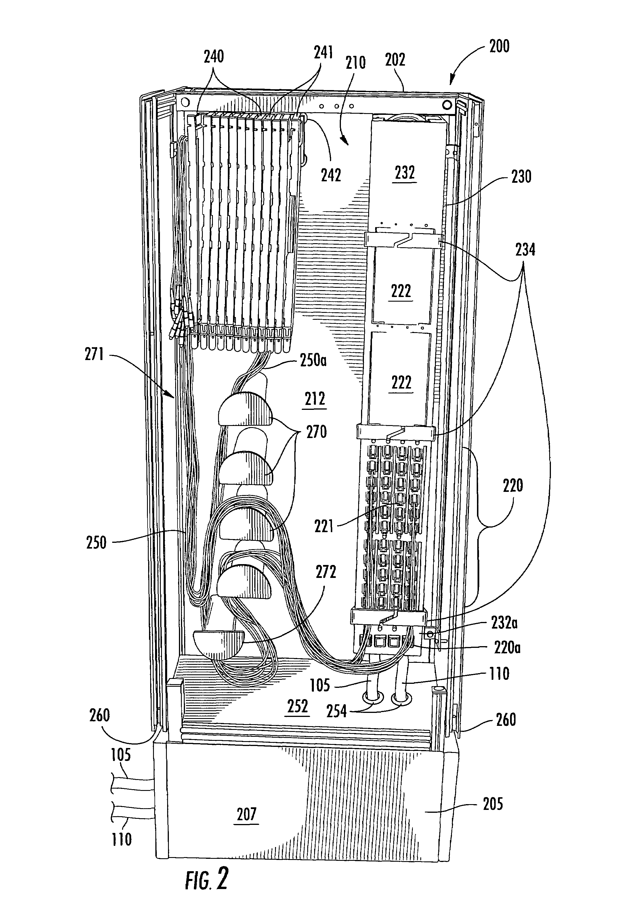
[0009]In other embodiments, the cross-connect module includes a plurality of tab members therein positioned to retain the loop of the optical fiber in the cross-connect module. A bend control member may be positioned between respective ones of the tab members configured to maintain the loop at a radius that at least equals a minimum bend radius of the optical fib...

Problems solved by technology

Typically, these varied length patchcords are routed in an unorganized fashion and may conflict with the recommended splitter module pigtail routing paths in the cabinet.

Method used


Image

  • Interconnect enclosures for optical fibers including cross-connect modules and methods for using the same
  • Interconnect enclosures for optical fibers including cross-connect modules and methods for using the same
  • Interconnect enclosures for optical fibers including cross-connect modules and methods for using the same

Examples


Embodiment Construction

[0025]The present invention now will be described more fully hereinafter with reference to the accompanying drawings, in which illustrative embodiments of the invention are shown. In the drawings, the relative sizes of regions or features may be exaggerated for clarity. This invention may, however, be embodied in many different forms and should not be construed as limited to the embodiments set forth herein; rather, these embodiments are provided so that this disclosure will be thorough and complete, and will fully convey the scope of the invention to those skilled in the art.

[0026]It will be understood that, although the terms first, second, etc. may be used herein to describe various elements, components, regions, layers and / or sections, there elements, components, regions, layers and / or sections should not be limited by these terms. These terms are only used to distinguish one element, component, region, layer or section from another region, layer or section. Thus, a first elemen...


PUM


Abstract

An interconnect device for optical fibers includes an enclosure. A first termination panel is mounted in the enclosure. The first termination panel has a plurality of optical fiber connection members, ones of which are associated with respective subscriber locations. A second termination panel is mounted in the enclosure that has a plurality of optical fiber connection members, ones of which are associated with respective input optical fibers associated with a service provider. A cross-connect module mounted in the enclosure has a loop of an optical fiber retained therein with a first and opposite second connectorized end of the optical fiber extending from the cross-connect module. The first and second connectorized ends of the optical fiber extend to a length sufficient to allow cross-connection of a selected pair of the connection members of the termination panels by connection of the connectorized ends thereto.

Description

BACKGROUND OF THE INVENTION[0001]The present invention relates to optical fiber products and, more particularly, to optical fiber cross-connect modules and methods for using the same.[0002]Optical fiber networks are increasingly being installed to support high-speed voice and data communications. Increasingly, the optical fiber coupling is being expanded out from the central office of the communication service provider companies, such as Regional Bell Operating Companies (RBOCs) to the subscriber locations, such as homes or businesses, where conventional copper wiring was traditionally used. Such alternate methods of providing bandwidth to subscriber locations are often referred to in the telecoms industry as Fiber to the Home (FTTH), Fiber to the Business (FTTB) and the like (FTTx).[0003]When providing services using an optical fiber network, it is generally necessary to add and drop subscribers over time. As a result, a variety of methods are provided for interconnecting subscribe...

Claims


Application Information

Patent Timeline
IPC IPC(8): G02B6/00
CPCG02B6/4453G02B6/4452G02B6/44524G02B6/44528
Inventor BRAGA, DAVID J.
Owner COMMSCOPE TECH LLC
Features
  • Generate Ideas
  • Intellectual Property
  • Life Sciences
  • Materials
  • Tech Scout
  • Unparalleled Data Quality
  • Higher Quality Content
  • 60% Fewer Hallucinations
Learn More