
Ground effects compensated angle of attack command system and method

a command system and ground effect technology, applied in process and machine control, instruments, navigation instruments, etc., can solve problems such as aircraft operating at less than its maximum performance characteristics, unstable or stalling,

Active Publication Date: 2008-07-29
SAFE FLIGHT INSTR LLC
View PDF3 Cites 3 Cited by
  • Summary
  • Abstract
  • Description
  • Claims
  • Application Information

AI Technical Summary

Problems solved by technology

In such cases, the aircraft may become unstable or stall.
However, in order to avoid unsafe conditions, a safety margin is provided for angle of attack and the aircraft is operated at less than its maximum performance characteristics.

Method used


Image

  • Ground effects compensated angle of attack command system and method
  • Ground effects compensated angle of attack command system and method
  • Ground effects compensated angle of attack command system and method

Examples


Embodiment Construction

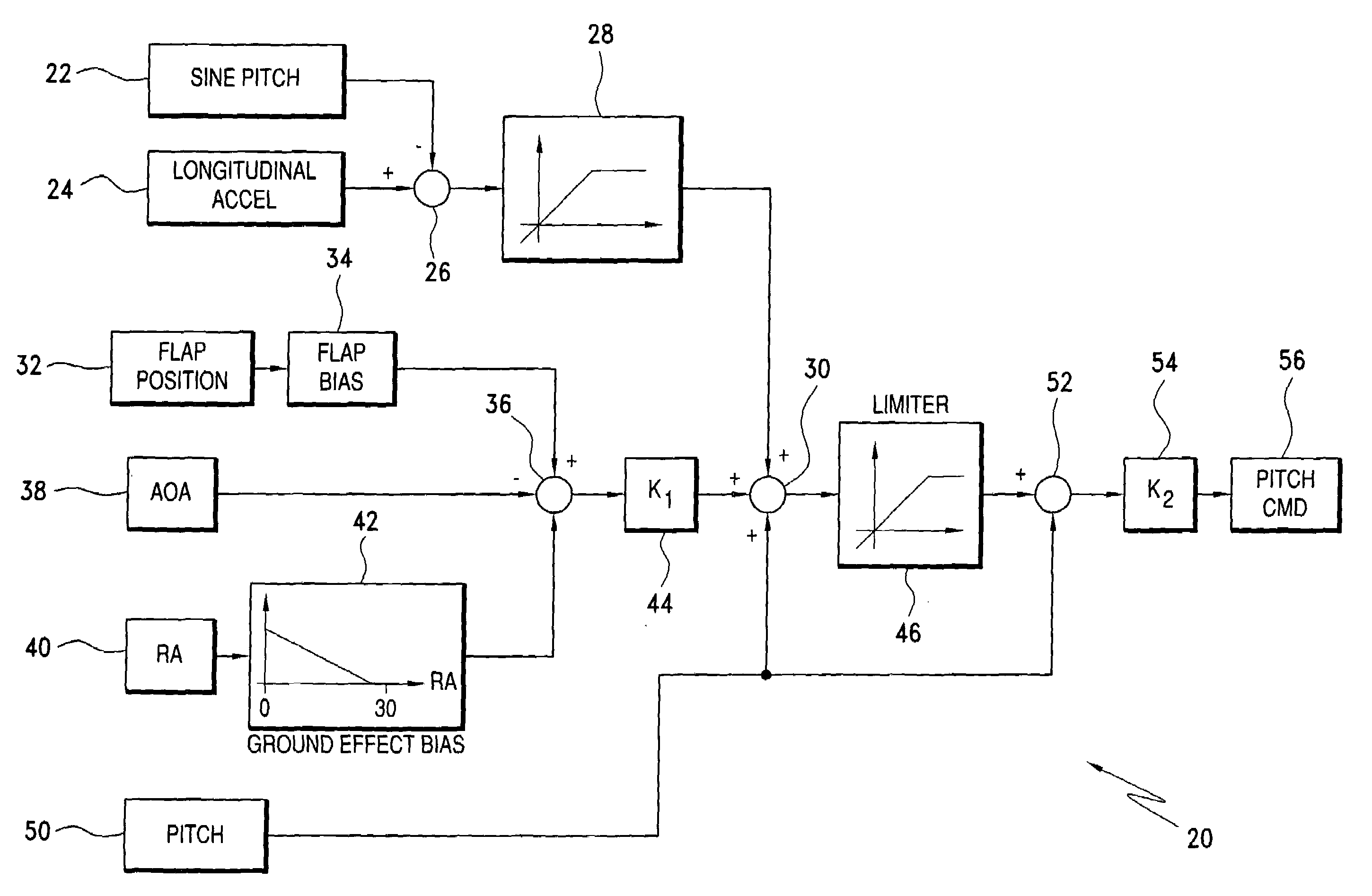
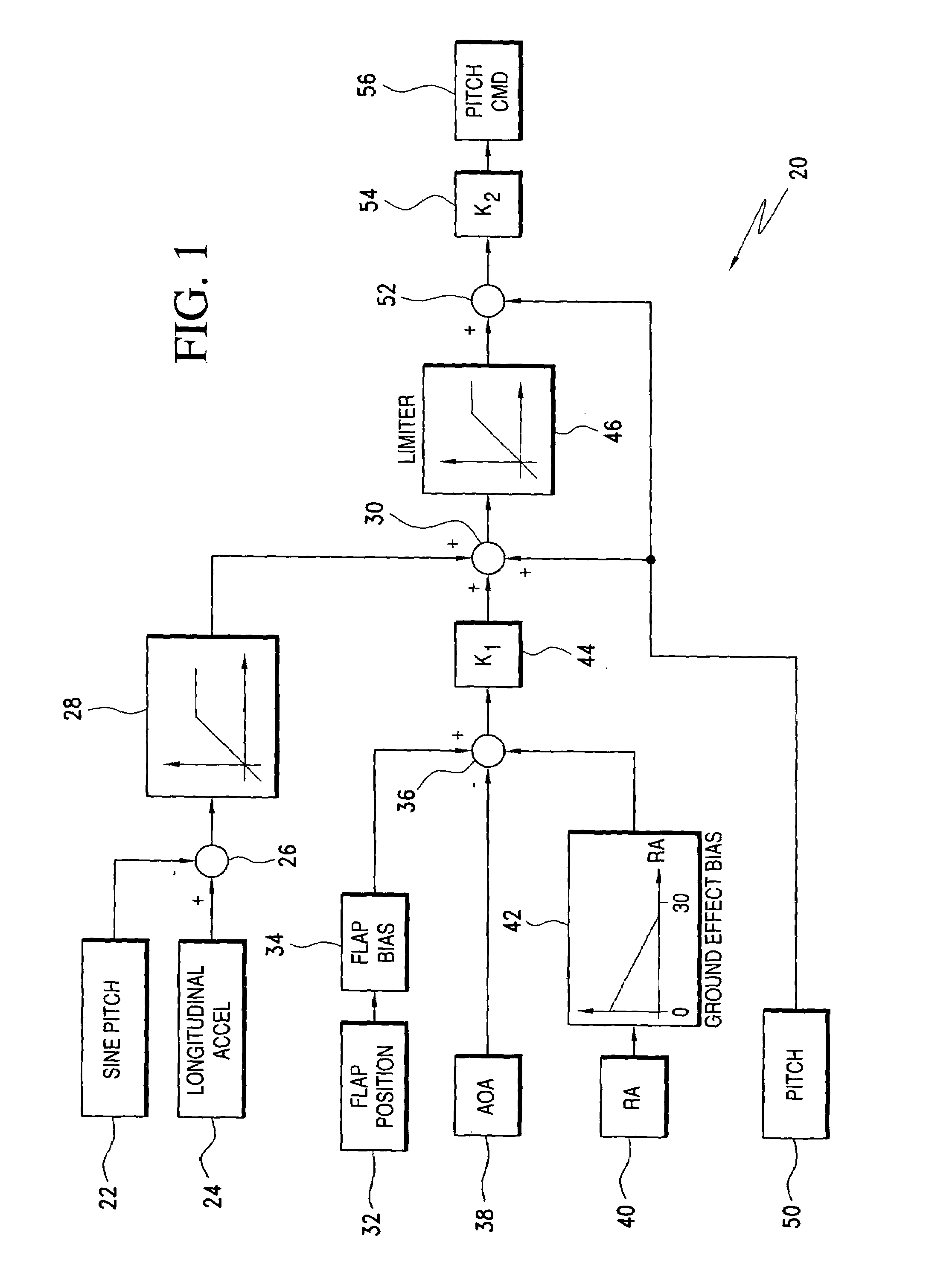
[0011]A ground effects compensation system for generating a compensated angle of attack system or command during a take-off of an aircraft is illustrated in FIG. 1. As illustrated, the ground effects compensation system is incorporated in a speed command system. One example of part of such system is disclosed in my earlier U.S. Pat. No. 4,520,060 which is incorporated herein in its entirety by reference.

[0012]Referring to FIG. 1, a speed command system 20 which includes a ground effects compensation system also includes conventional means 22 for generating a signal indicative of the sine of the pitch angle of the aircraft and a conventional longitudinal accelerometer 24. Signals generated by the means 22 and longitudinal accelerometer 24 are fed to a summing junction 26, the output of which is fed to a positive limiter circuit 28. The positive limiter circuit 28 restricts the acceleration output to avoid approaching a stall.

[0013]A flap position sensor 32 sends a signal to a flap bi...


PUM


Abstract

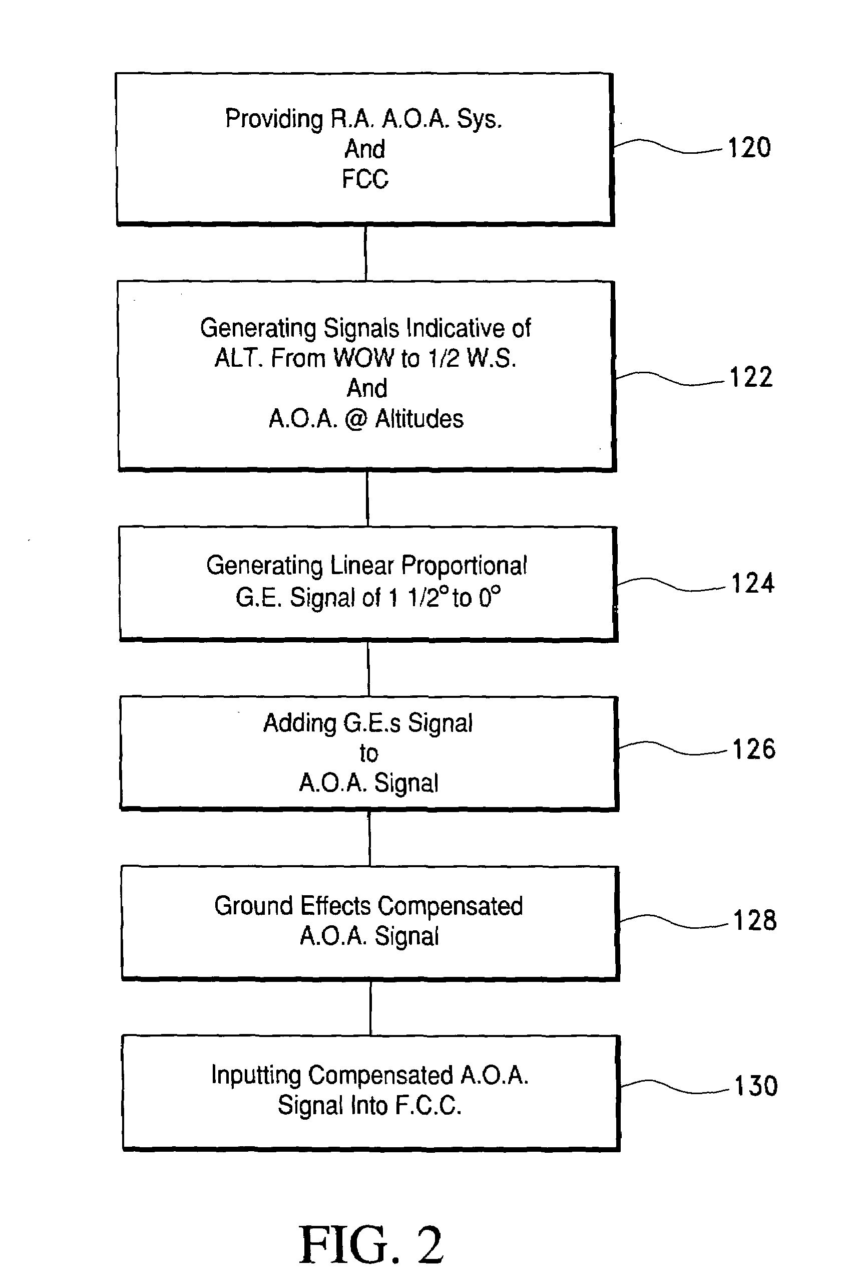
A take off ground effects compensated angle of attack system includes a radio altimeter and / or timer, a pitch angle system and a flight control computer. The radio altimeter generates a signal which is indicative of the aircraft's altitude from 0 i.e., weight off wheels to an altitude of ½ the wing span of the aircraft. The angle of attack system simultaneously generates a signal which is indicative of the aircraft's angle of attack without compensation for ground effects. Therefore, a ground effects signal of from 1½° to 0° is generated and added to the angle of attack signal as the aircraft climbs from 0 ft. to an altitude which is equal to ½ the wing span of the aircraft. The ground effects signal is added to the angle of attack signal to provide a ground effects compensated angle of attacks signal which is then fed to the flight control computer or display.

Description

FIELD OF THE INVENTION[0001]This invention relates to a method and system for generating a ground effects compensated angle of attack signal during a takeoff of an aircraft and more particularly to an angle of attack command system that is compensated for ground effects during a period from weight off wheels until an altitude which is equal to about one half the wing span of the aircraft.BACKGROUND FOR THE INVENTION[0002]A method for generating a ground effect compensated aircraft body angle of attack signal is disclosed in the U.S. Pat. No. 5,089,968 of Orgun et al. As disclosed therein, the method includes converting an aircraft pitch rate correction alpha vane signal to a free air body angle of attack signal that is collaborated to the type of aircraft that employs the method for the two conventional landing flap settings. The free air body angle and attack signal is processed to obtain an alpha vane correction signal that represents ground effects compensation that would be requ...

Claims


Application Information

Patent Timeline
Patent Type & Authority Patents(United States)
IPC IPC(8): G05D1/06
CPCG05D1/0661
Inventor GREENE, LEONARD M.
Owner SAFE FLIGHT INSTR LLC
Learn More