Eureka AIR delivers breakthrough ideas for toughest innovation challenges, trusted by R&D personnel around the world.
Multiple-passenger transporter
What is Al technical title?
Al technical title is built by PatSnap Al team. It summarizes the technical point description of the patent document.
a multi-passenger, transporter technology, applied in the field of transporters, can solve the problems of hard or impossible for either person to govern the motion of the device by leaning, and achieve the effect of dynamic maintenance of the stability of the first support platform
Inactive Publication Date: 2008-08-05
DEKA PROD LLP
View PDF162 Cites 33 Cited by
Summary
Abstract
Description
Claims
Application Information
AI Technical Summary
This helps you quickly interpret patents by identifying the three key elements:
Problems solved by technology
Method used
Benefits of technology
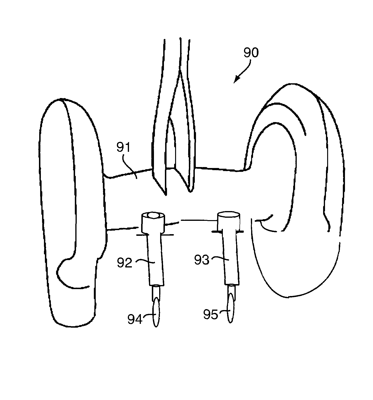
[0010]In accordance with further related embodiments of the invention, at least one of the passenger platforms is coupled to the first platform via a ball joint or a U-joint. At least one of the passenger platforms may include a substantially vertical support column. At least one of the passenger platforms may include both a right support platform for supporting a rider's first foot, and a left support platform for supporting the rider's second foot. The controller may command the motorized drive arrangement such that stability of the first support platform is dynamically maintained.
Problems solved by technology
However, a problem arises when there is more than one rider.
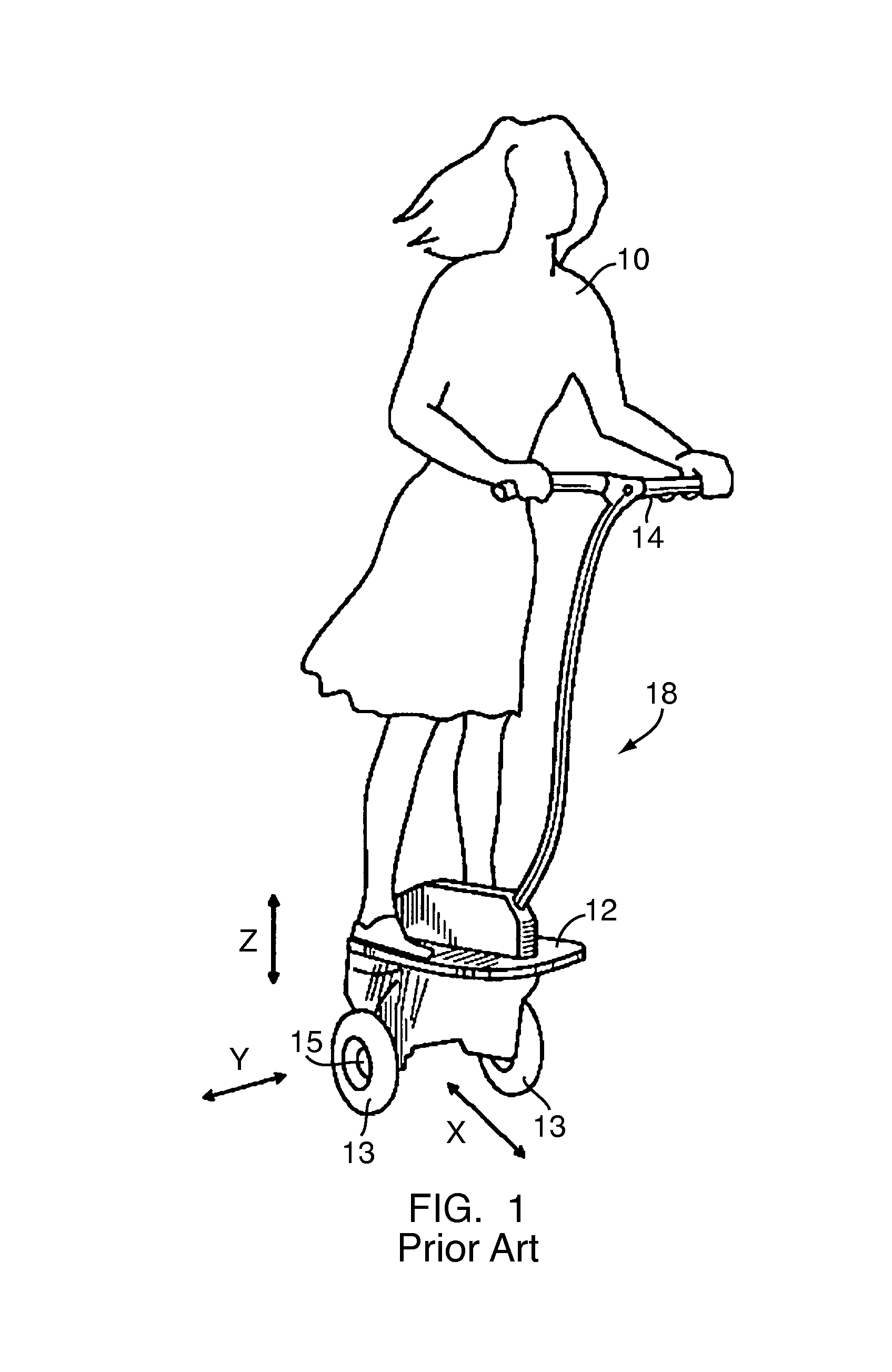
While it may be relatively simple for a single rider to lean in a given direction so as to control the motion of the transporter, placement of a second person on the transporter may make it hard or impossible for either person to govern motion of the device by leaning.
Method used
Image
Click on the blue label to locate the original text in one second.
Reading with bidirectional positioning of images and text.
Examples
Embodiment Construction
[0025]In accordance with one embodiment of the invention, FIGS. 3 and 4 show a side and perspective view, respectively, of a transporter 30 for transporting riders, over the ground or other surface, which may be referred to herein generally as ground. Transporter 30 may be a dynamically balanced transporter, or alternatively, may be statically stable with respect to tipping. Transporter 30 includes a first support platform. A first rider may, for example, stand or sit on first support platform 31. Attached to first support platform 31 may be a handlebar 32 that can be gripped by a rider while situated on first support platform 31.
[0026]Coupled to first support platform 31 are one or more ground-contacting elements 33, 34, which provide contact between first support platform 31 and the ground. Ground-contacting elements 33, 34 may include, but are not limited to, arcuate members, tracks, treads, and wheels (hereinafter the term “wheel” will be used in the specification to refer to an...
PUM
Abstract
A transporter for transporting a first person and one or more riders over a surface. The transporter includes a first support platform for supporting the first person, the first support platform having left and right sides and defining a fore-aft vertical plane and a lateral plane. At least one ground-contacting element is coupled to the first support platform such that the first support platform is capable of tilting in the fore-aft plane about a tilt axis. The at least one ground-contacting element is driven by a motorized drive arrangement so as to cause locomotion of the transporter. A controller commands the motorized drive arrangement. The controller is configured so that at least one of fore and aft sustained motion of the transporter is based at least on fore-aft tilting of the first support platform. One or more passenger platforms support one or more riders, the passenger platforms coupled to the first support platform such that fore-aft tilting of the first support platform is substantially independent of the one or more passenger platforms.
Description
[0001]The present application is a divisional of U.S. patent application Ser. No. 10 / 618,914, filed Jul. 14, 2003, now U.S. Pat. No. 6,969,079 which is a continuation-in-part of U.S. application Ser. No. 10 / 164,333, filed Jun. 5, 2002 now abandoned. The present application is also a continuation-in-part of U.S. patent application Ser. No. 10 / 626,468, filed Jul. 24, 2003, which is a continuation-in-part of U.S. patent application Ser. No. 10 / 164,333, filed Jun. 5, 2002, now abandoned which is a divisional of U.S. patent application Ser. No. 09 / 516,384, filed Mar. 1, 2000, and which is now U.S. Pat. No. 6,435,535. All of the aforementioned patents and patent applications are hereby expressly incorporated herein by reference in their entirety.TECHNICAL FIELD AND BACKGROUND ART[0002]The present invention generally relates to a transporter and method for transporting one or more persons, and more particularly, to a transporter whose sustained motion is controlled, at least in part, by le...
Claims
Application Information
Patent Timeline
Application Date:The date an application was filed.
Publication Date:The date a patent or application was officially published.
First Publication Date:The earliest publication date of a patent with the same application number.
Issue Date:Publication date of the patent grant document.
PCT Entry Date:The Entry date of PCT National Phase.
Estimated Expiry Date:The statutory expiry date of a patent right according to the Patent Law, and it is the longest term of protection that the patent right can achieve without the termination of the patent right due to other reasons(Term extension factor has been taken into account ).
Invalid Date:Actual expiry date is based on effective date or publication date of legal transaction data of invalid patent.