Man-powered ornithopter-sailplane

a technology of flying devices and aircraft, applied in the field of man-powered ornithopters, can solve the problems of negative aerodynamic force directed downward, imperfect aerodynamic profile of the flying device, and the apparatus cannot fly at slow speed, and achieve the effect of smooth descen

Inactive Publication Date: 2008-08-12
DAINYS REMIGIJUS +2
View PDF5 Cites 12 Cited by
  • Summary
  • Abstract
  • Description
  • Claims
  • Application Information

AI Technical Summary

Benefits of technology

[0005]The purpose of this invention is to increase in every way the possibilities of a human pilot to make the most effective use of the power from all the strongest muscle groups: thighs, torso, shoulders, and arms, which would allow him to selectively fly in turns by flapping his wings or gliding, smoothly descend, manoeuvre easily, and steer it during such a flight with effective propulsion and guiding mechanisms adapted for this.
[0006]The specified aim is achieved by using two muscular propulsion engines: a femoral propulsion engine and a humeral propulsion engine in accordance with USSR invention certificate of authorship no. 945 491 of R. Dainys, the creator of this invention, and in accordance with international publication WO 03 / 035186 of an invention of R. Dainys. The invention of a muscular propulsion ornithopter-sailplane is intended to create an opportunity for a human pilot to use only the power of his own muscles to take off, fly by flapping his wings or gliding, manoeuvre freely, make various turns, and gradually or abruptly descend by reducing the speed of the descent and the flying speed and by reducing them to practically zero at the moment of landing. Such flying and gliding possibilities can be created by using both the first and the second variant of the muscular propulsion ornithopter-sailplane characterised by fundamental new features so that thanks to femoral and humeral propulsion engines the principal parts of the person's body which are joined and securely attached to them: the torso, thighs, shoulders, upper arms, and arms become a single integrated propelled-steered mechanism for flight. According to the first variant, the ornithopter-sailplane has one pair of flapping wings and a hang glider wing. According to the second variant, the ornithopter-sailplane has two pairs of flapping wings and a hang glider wing. The delta shaped-hang glider wing is used in this invention only as a well-mastered flying apparatus, although any other construction having markedly better aerodynamic profile parameters than a delta-shaped wing, could be much more effectively used in its place.
[0008]The fundamentally original flapping wings have wing panels with rotatable stiff rods, to which are attached, asymmetrically to the rods' axes, stiff feather-like panels, which narrow at the ends and create a broken aerodynamic profile at the end of the wing with intervals between the adjacent feather-like panels and a solid aerodynamic profile in the middle of the wing when gliding or during the downward flapping movement of the wing. This profile creates increased lift and propulsion aerodynamic forces, which are created by the strong air whirls and flows created in the intervals between these panels due to the lengthwise and rotated deformations of the rods and due to bending deformations of the posterior edges of the feather-like panels. This wing construction during the period of its movement upwards and backwards forces the feather-like panels to rotate and changes them into a broken wing consisting of a row of rotated feather-like panels creating not only lifting but also forward propulsion forces. This effective action of the flapping wings is very important in the initial period of the ornithopter's ascent, which can create possibilities for the pilot to rise vertically or by flapping the wings to briefly hover by staying at one height.
[0009]The construction of the first variant of the ornithopter-sailpiane creates essentially new possibilities to perform such guiding-steering movements. The direct kinematic connection between the femoral arms and the wings allows the pilot to set one or both wings in positions with different angles by fixing the thighs in corresponding positions, by the thighs moving at different speeds, or by letting them lag according to the phases of the flapping cycle when each change in the angle of the declination of the flapping wings simultaneously changes the balance of the aerodynamic forces of these wings and creates possibilities for the pilot to make turns with just the uneven movements of the thighs.

Problems solved by technology

A serious deficiency of the flapping wings of these flying devices is their imperfect aerodynamic profiles: the movement of the rods during the wings' rising-upbeat cycle creates a negative aerodynamic force directed downward.
Thus these apparatuses cannot fly at slow speeds.

Method used


Image

  • Man-powered ornithopter-sailplane
  • Man-powered ornithopter-sailplane
  • Man-powered ornithopter-sailplane

Examples


Embodiment Construction

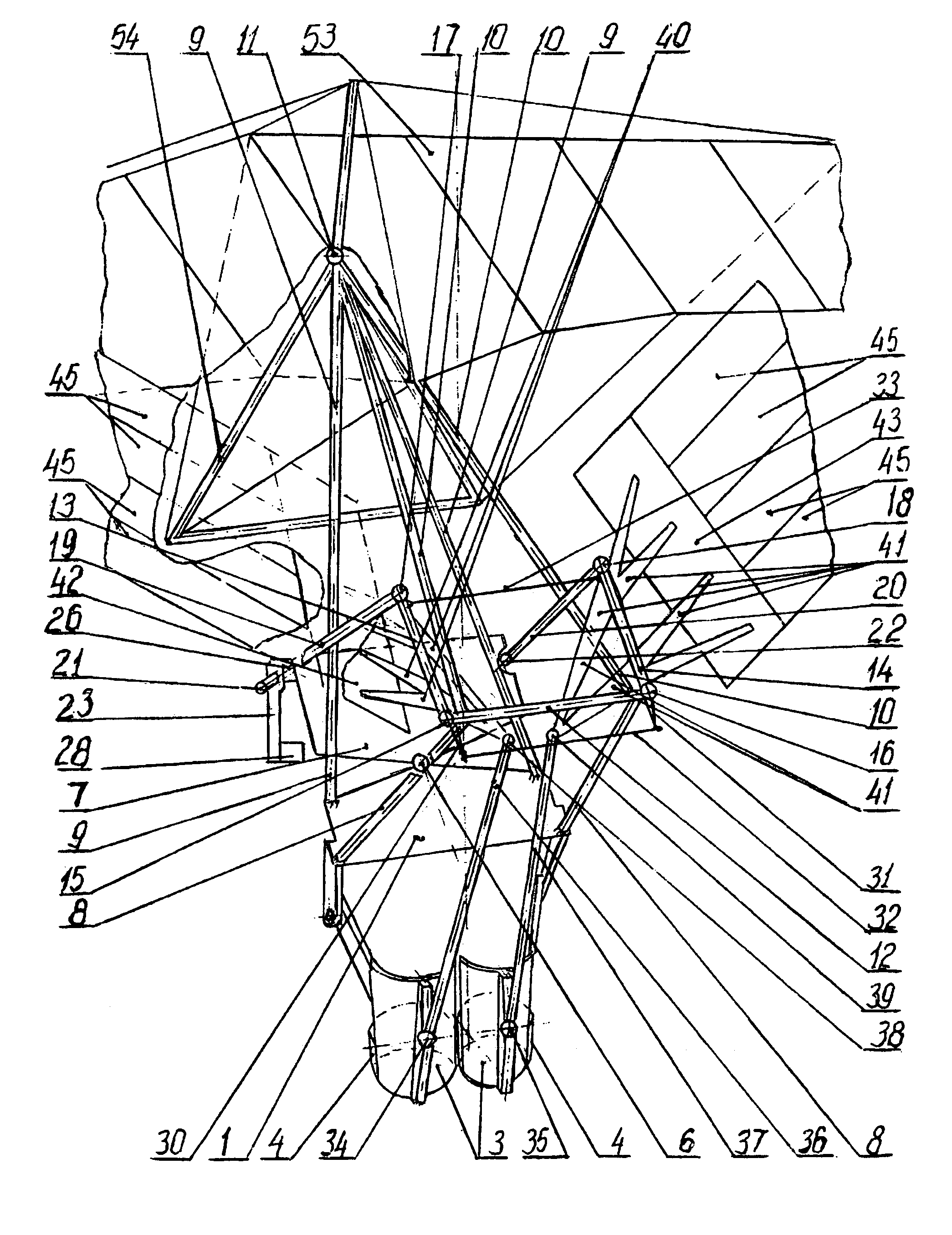
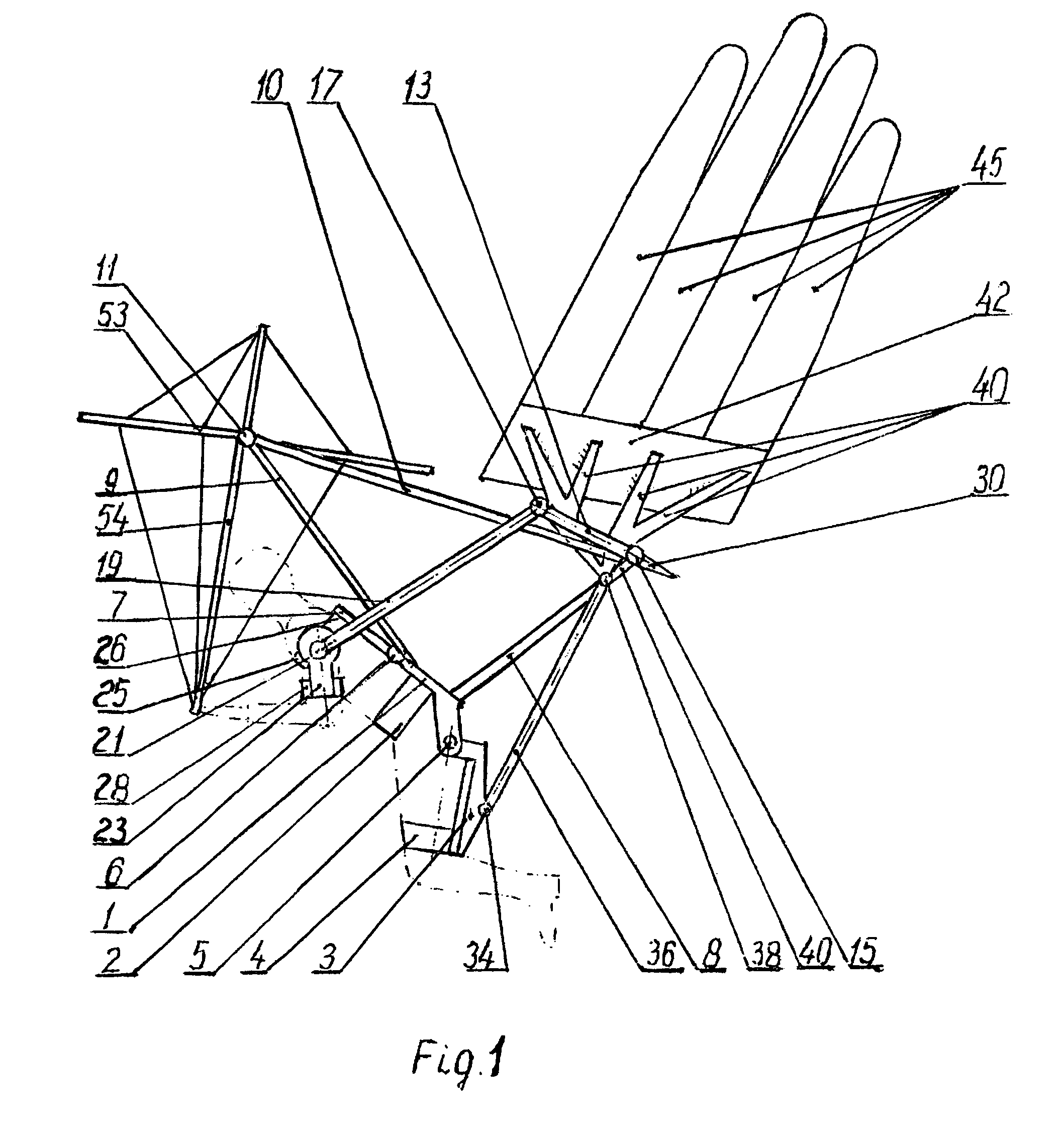
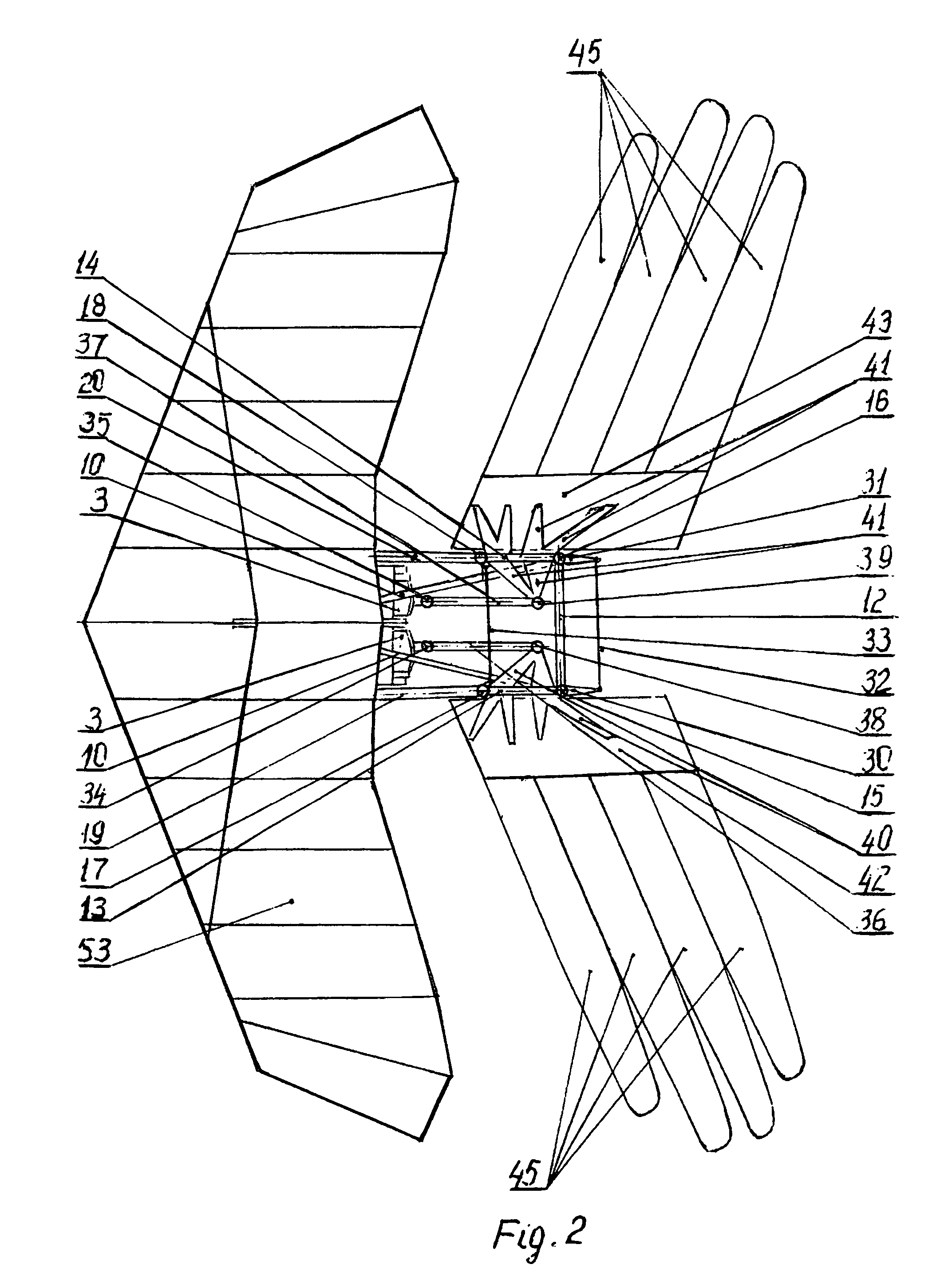
[0027]A man-powered ornithopter-sailplane according to the first variant with femoral and humeral propulsion engines in accordance with USSR certificate of authorship no. 945 941 and in accordance with international invention publication WO 03 / 035 186 having torso base 1, torso strap 2, two femoral arms 3 with thigh straps 4, two axles 5 joining torso base 1 to femoral arms 3. Torso base I is connected in the front by sliding ball or cardan joint 6 to shoulder base 7 in front of it. To the edges of torso base 1 are attached the frame's left and right framework, which consists of strip pairs 8, 9, 10. The strip pairs 9, 10 converge in the front, are joined together, and are attached to ball or cardan joint 11. Created from strip pairs 8, 10, the frame's posterior corners are connected by strip 12. The left 15 and right 16 ball joints of the left 13 and right 14 wing axles of the flapping wings are rigidly attached respectively to the left and right corners created by strips 8, 10. Wi...


PUM


Abstract

A man-powered ornithopter-sailplane, which has one or two pair of flapping wings and a hang-glider wing wherein substantially novel femoral and humeral muscular propulsion engines with the aid of which the body members connected thereto form integrated moving-flying and controlling-guiding mechanisms. Femoral arms are fixed to the torso base from which the movements for the wings flapping with respect to axles inclined to a horizontal direction are transmitted through the intermediate links of a kinematic chain. The wings comprise a row of rotational rods arranged therein and provided with elastic feather-like panels which produced during flapping, in a closed or turned position thereof, aerodynamic profiles and corresponding lifting and propulsion aerodynamic forces. The controlling-guiding movements are transmitted from the humeral arms to the flapping wings using movable ball joints. The diversity of movements of the femoral arms, humeral arms, hang-glider wing make it possible to control the flight.

Description

RELATED APPLICATION[0001]This application is a national stage application based on PCT / LT2004 / 000002 filed on Mar. 31, 2004, which claims priority from Lithuania application 2003 081 filed Sep. 11, 2003.FIELD OF THE INVENTION[0002]The invention relates to man-powered flying devices.BACKGROUND OF THE INVENTION[0003]A sailplane-ornithopter, which has two pairs of flapping wings, links, cables, interconnected rods, and loops is known (USSR patent no. 1205, 64 C 33 / 02). A man-powered flying device with two flapping wings, and two different variants of stands and arms pedals, and links is known (M. K. Tichonov Moscow. 1949, pp. 168).[0004]A motorised ornithopter with flapping wings with feather-shaped panels, where a mechanism automatically controls the rotation of its rods to the necessary angle, is known (USSR, certificate of authorship no. 187 533). A flying apparatus with inclined horizontal wing axes, two flapping wings consisting of a wing panel with a solid part and a second part ...

Claims


Application Information

Patent Timeline
Patent Type & Authority Patents(United States)
IPC IPC(8): B64C33/00B64C33/02
CPCB64C33/025B64C33/00
Inventor DAINYS, REMIGIJUS
Owner DAINYS REMIGIJUS
Why Eureka
Try Eureka