Magnetic attachment for a walking cane

a technology of magnetic attachment and walking cane, which is applied in the field of magnetic attachment of walking cane, can solve the problems of individuals falling over or sustaining back injuries, unable to bend over or kneel down to recover fallen objects, and difficulty in retrieving various objects, etc., and achieves the effect of quick and easy coupling

Inactive Publication Date: 2008-09-02
REEVES TIMOTHY
View PDF14 Cites 3 Cited by
  • Summary
  • Abstract
  • Description
  • Claims
  • Application Information

AI Technical Summary

Benefits of technology

[0008]In general terms, disclosed herein is a magnetic attachment to be quickly and easily coupled to a conventional walking cane of the type having a handle at the top end thereof to be grasped in the hand of an elderly or disabled individual. More particularly, the magnetic attachment includes a magnet that is coupled to the handle end of the walking cane. By turning the cane upside down, the magnetic attachment at the handle end can be moved into contact with a magnetic object, such as a set of keys, or the like. The magnet of the magnetic attachment exerts an attractive force to hold the magnetic object against the handle end of the cane so that the object can be lifted off the floor and carried to the user's hand. By virtue of the foregoing, the user will not have to bend over or kneel down to retrieve an object which has inadvertently fallen on the floor.

Problems solved by technology

Because of age, infirmity, or disability, it is sometimes difficult for these individuals to retrieve various objects (e.g., a set of keys, or the like), that has fallen on the floor.
In particular, having to bend over or kneel down to recover a fallen object may not be possible in some cases.
In other cases, individuals could fall over or sustain back injury during the attempt to pick up an object which has been inadvertently dropped on the floor.
However, the devices shown in the above-identified patents are generally complex, relatively expensive and require manipulative skills.
Consequently, such devices may not be readily available or suitable to many of those in need of a lifting aid.

Method used


Image

  • Magnetic attachment for a walking cane
  • Magnetic attachment for a walking cane
  • Magnetic attachment for a walking cane

Examples


Embodiment Construction

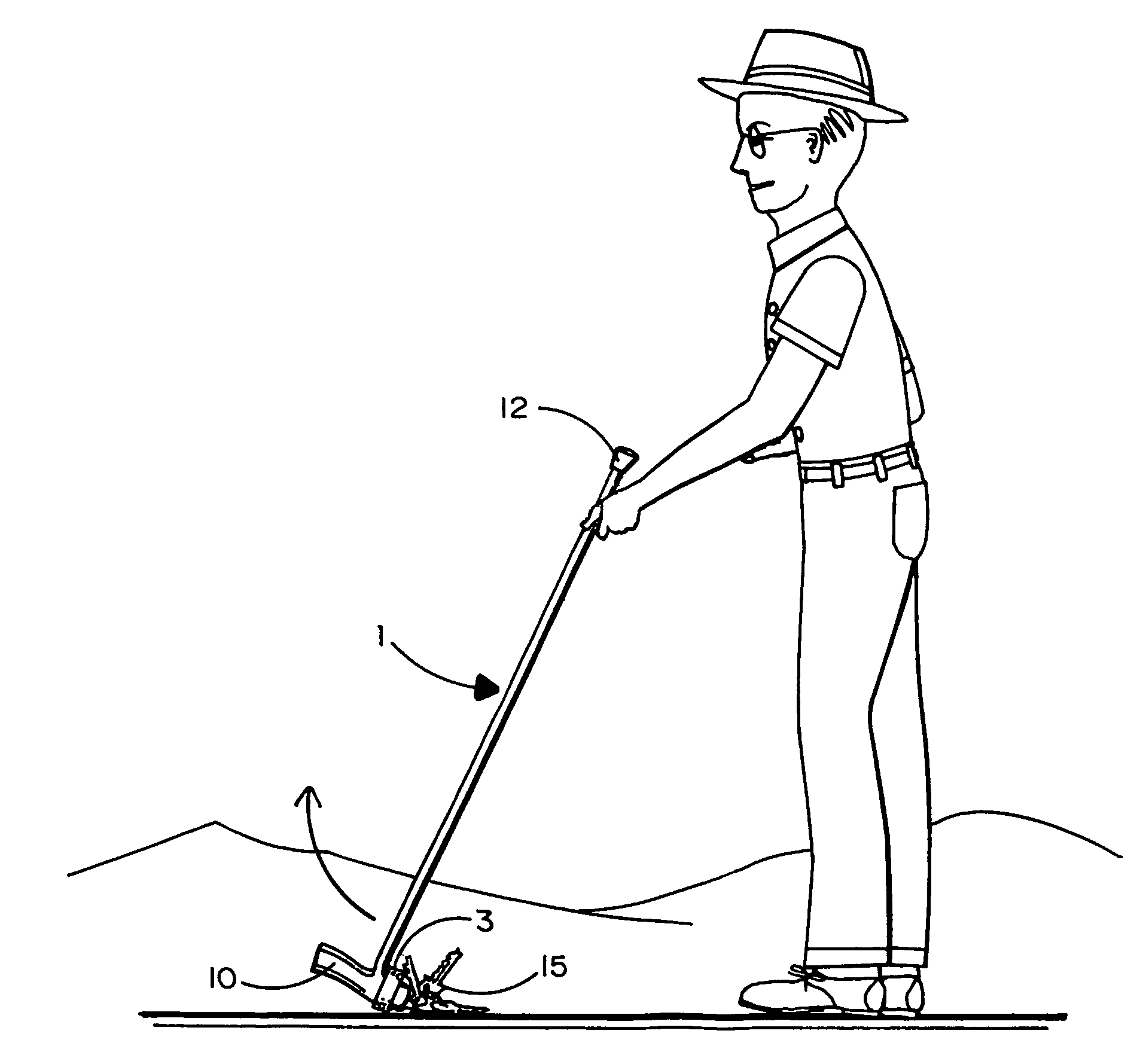
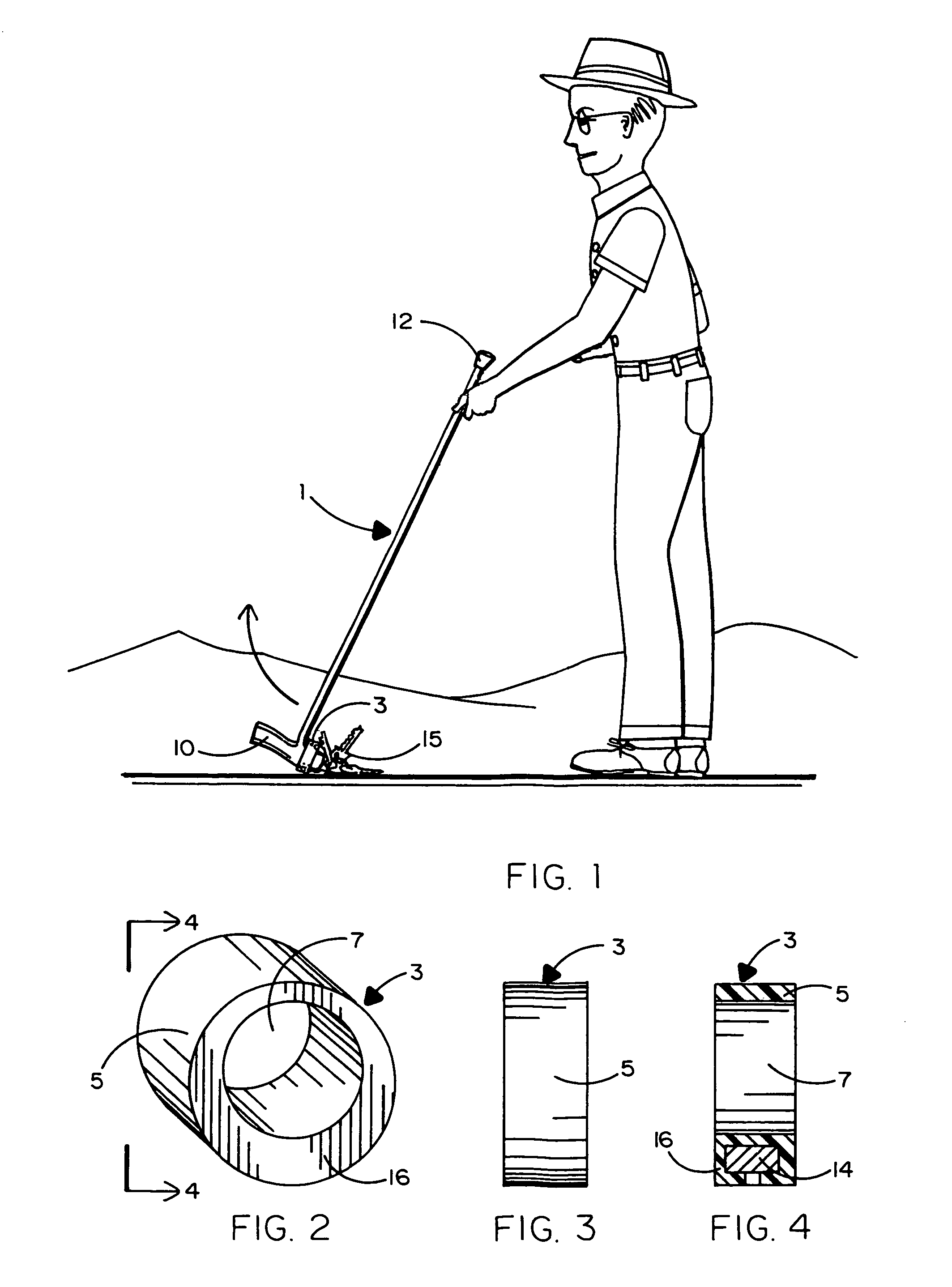
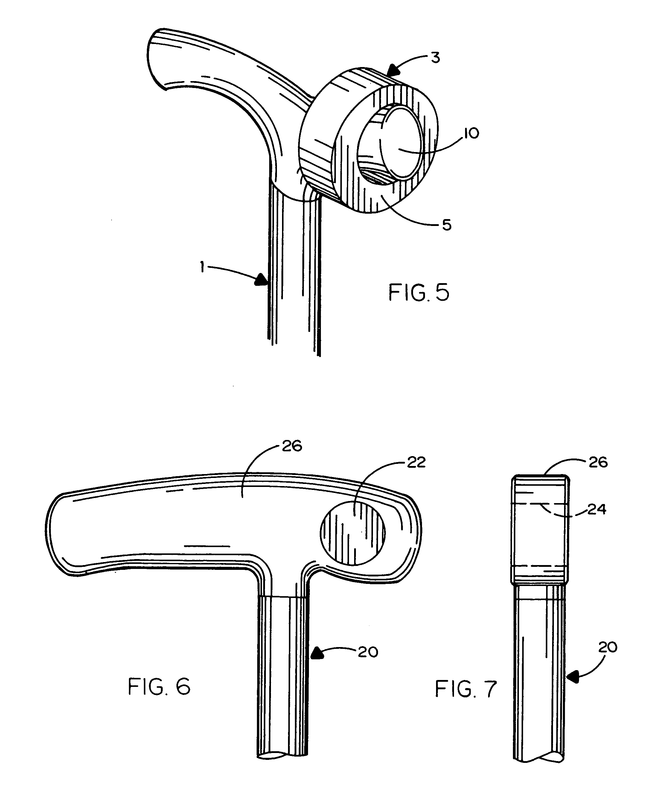
[0018]Referring initially to FIGS. 1-5 of the drawings, there is shown in FIG. 1 an individual using a conventional walking cane 1 to assist him in walking or standing. According to the present improvement, a magnetic attachment 3 (best shown in FIGS. 2-4) is detachably coupled to the cane 1 to allow the user to lift metal objects off the ground without having to kneel down or bend over. In the example of FIG. 1, the metal object to be attracted to the magnetic attachment 3 coupled to cane 1 is a set of keys 15. However, the combination walking cane 1 and magnetic attachment 3 can be used to lift other magnetic objects that are capable of being attracted to and held against a magnet in a manner that will soon be described. By virtue of using the combination cane 1 and magnetic attachment 3 herein disclosed, an elderly or disabled individual will not be as susceptible to the possibility of falling or sustaining a back injury while attempting to retrieve his dropped keys, or the like,...


PUM


Abstract

A magnetic attachment is disclosed to be coupled to a conventional walking cane at the handle end thereof that is grasped by the hand of a user. By turning the cane upside down, the magnetic attachment at the handle end can be moved into contact with a magnetic object (e.g., a set of keys) to be lifted off the floor and carried to the hand of the user. By virtue of the foregoing, an elderly or disabled individual will not have to bend over or kneel down to retrieve his dropped keys, or the like. In a first embodiment, the magnetic attachment is a coupling ring that is molded over and around a magnet. The coupling ring has a longitudinally extending channel that is sized to removably receive and surround the handle end of the walking cane. In a second embodiment, the magnetic attachment is a magnet that is retained within a hole that extends laterally through the handle end of the cane.

Description

CROSS-REFERENCE TO RELATED U.S. PATENT APPLICATIONS[0001]This patent application is related to Provisional Patent Application No. 60 / 597,187 filed Nov. 15, 2005.BACKGROUND OF THE INVENTION[0002]1. Field of the Invention[0003]This invention relates to a magnetic attachment coupled to the handle end of a conventional walking cane by which to enable elderly or disabled individuals to retrieve dropped metal objects, such as a set of keys, or the like, without having to bend over or kneel down.[0004]2. Background Art[0005]Individuals who are elderly or disabled, including those who may have suffered a physical injury, are often required to use a walking cane when moving from place to place. Because of age, infirmity, or disability, it is sometimes difficult for these individuals to retrieve various objects (e.g., a set of keys, or the like), that has fallen on the floor. In particular, having to bend over or kneel down to recover a fallen object may not be possible in some cases. In othe...

Claims


Application Information

Patent Timeline
Patent Type & Authority Patents(United States)
IPC IPC(8): A45B3/00
CPCA45B3/00A45B2009/002A45B9/02
Inventor REEVES, TIMOTHY
Owner REEVES TIMOTHY
Why Eureka
Try Eureka