Flow control device for choking inflowing fluids in a well

a well and fluid flow technology, applied in the direction of drinking water installation, fluid removal, construction, etc., can solve the problems of large viscosity variation, large viscosity variation, and large variability of the production rate of the well

Inactive Publication Date: 2008-09-02
RESLINK
View PDF48 Cites 127 Cited by
  • Summary
  • Abstract
  • Description
  • Claims
  • Application Information

AI Technical Summary

Problems solved by technology

This particularly concerns those disadvantages and problems associated with viscosity fluctuations of the inflowing reservoir fluids during recovery of hydrocarbons from at least one underground reservoir via a horizontal well.

Method used


Image

  • Flow control device for choking inflowing fluids in a well
  • Flow control device for choking inflowing fluids in a well
  • Flow control device for choking inflowing fluids in a well

Examples


first embodiment

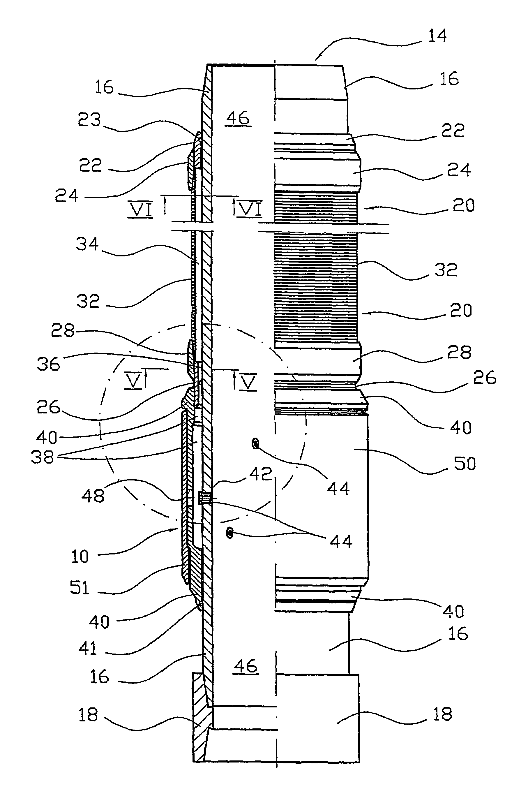
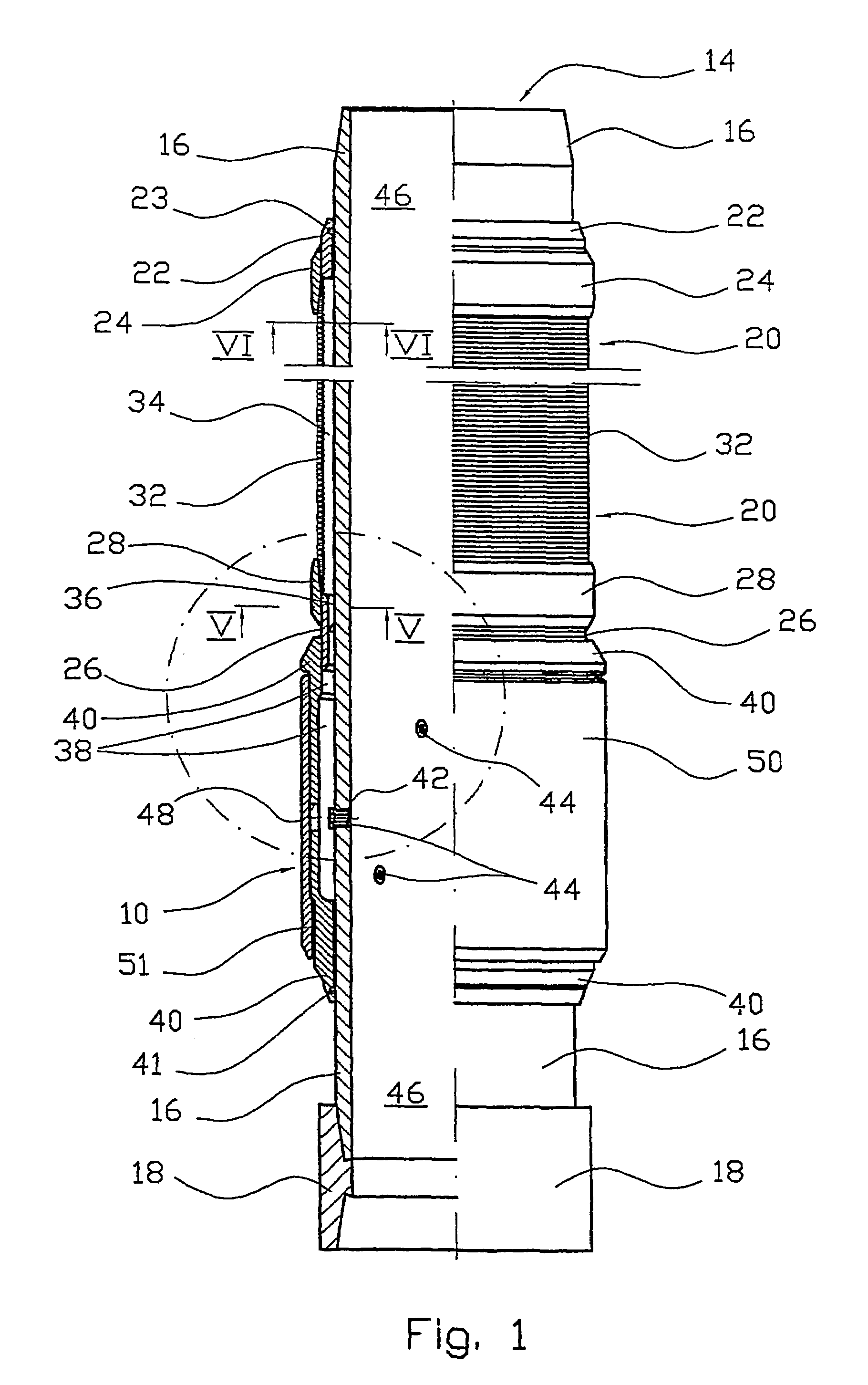
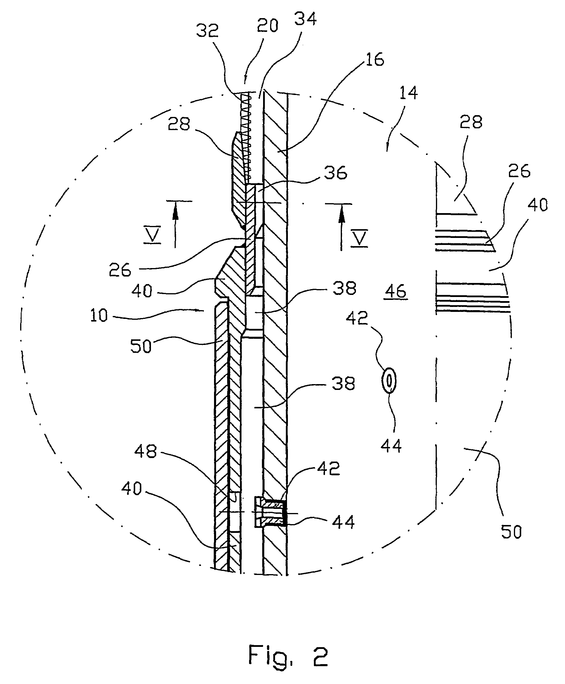
[0063]In the invention, cf. FIG. 1 and FIG. 2, reservoir fluids are flowing into an annulus 38 in the flow control device 10. The annulus 38 consists of the cavity existing between the base pipe 16 and an enclosing and tubular housing 40 having circular cross section. The upstream end portion of the housing 40 encloses the connecting sleeve 26, while the downstream end portion of the housing 40 encloses the pipe 16. In this embodiment the downstream end portion of the housing 40 is fitted with an internal ring gasket 41. A portion of the pipe 16 being in direct contact with the annulus 38, is provided with several through-going and threaded insert bores 42 of identical bore diameter. A corresponding number of externally threaded and pervasively open nozzle inserts 44 are removably placed in the insert bores 42. The nozzle inserts 44 may be of one specific internal nozzle diameter, or they may be of different internal nozzle diameters. All fluids flowing in through the sand screen 20...

second embodiment

[0064]In the invention, cf. FIG. 3 and FIG. 4, reservoir fluids are flowing from said connecting sleeve 26 and onwards in a downstream direction into a first annulus 52 of the flow control device 12. The annulus 52 consists of the cavity existing between the base pipe 16 and an enclosing and tubular housing 54 having circular cross section, the annulus 52 forming an integral part of the housing 54. The upstream end portion of the housing 54 encloses the connecting sleeve 26, while the downstream end portion of the housing 54 is provided with an annular collar section 56 enclosing the pipe 16, and extending into said cavity. In this embodiment the collar section 56 is fitted with an internal ring gasket 58. Moreover, the collar section 56 is provided with several axially through-going and threaded insert bores 60 distributed along the circumference thereof, the bores 60 having identical bore diameters. A corresponding number of threaded and pervasively open nozzle inserts 62 are remo...


PUM


Abstract

A flow arrangement (10, 12) for use in a well through one or more underground reservoirs, and where the arrangement (10, 12) is designed to throttle radially inflowing reservoir fluids produced through an inflow portion of the production tubing in the well, the production tubing in and along this inflow portion being provided with one or more arrangements (10, 12) Such an arrangement (10, 12) is designed to effect a relatively stable and predictable fluid pressure drop at any stable fluid flow rate in the course of the production period of the well, and where said fluid pressure drop will exhibit the smallest possible degree of susceptibility to influence by differences in the viscosity and / or any changes in the viscosity of the inflowing reservoir fluids during the production period. Such a fluid pressure drop is obtained by the arrangement (10, 12) comprising among other things one or more short, removable and replaceable flow restrictions such as nozzle inserts (44, 62), and where the individual flow restriction may be given the desired cross section of flow, through which reservoir fluids may flow and be throttled, or the flow restriction may be a sealing plug.

Description

CROSS REFERENCE TO RELATED APPLICATION[0001]The present application is the U.S. national stage application of International Application PCT / NO02 / 00105, filed Mar. 15, 2002, which international application was published on Sep. 26, 2002 as International Publication WO 02 / 075110. The International Application claims priority of Norwegian Patent Application 20011420, filed Mar. 20, 2001.AREA OF USE FOR THE INVENTION[0002]The present invention concerns a flow control device for choking pressures in fluids flowing radially into a drainage pipe of a well, preferably a petroleum well, while producing said fluids from one or more underground reservoirs. Said drainage pipe hereinafter is termed production tubing.[0003]Preferably, the flow control device is used in a horizontal or approximately horizontal well, hereinafter simply termed horizontal well. Such flow control devices are particularly advantageous when used in wells of long horizontal extent. The invention, however, may equally wel...

Claims


Application Information

Patent Timeline
Patent Type & Authority Patents(United States)
IPC IPC(8): E21B43/12E21B17/18
CPCE21B43/12E21B17/18
Inventor DYBEVIK, ARTHURCHRISTENSEN, OVE SIGURDMOEN, TERJE
Owner RESLINK
Why Eureka
Try Eureka