
Security fence module

a technology of security fences and modules, applied in barbed wires, building types, construction, etc., can solve the problems of low detection quality, physical delay properties are reduced, and the quality of detection needs to be balanced with adequate delay

Inactive Publication Date: 2008-09-02
SAFEGUARDS TECH
View PDF11 Cites 11 Cited by
  • Summary
  • Abstract
  • Description
  • Claims
  • Application Information

AI Technical Summary

Benefits of technology

"The present invention provides a fence section with a unique design that includes multiple vertical supports and a first sensing module to detect vibrations. The fence section is made up of a first planar fence section, a second planar fence section, and a third fence section that forms an acute angle with the base frame. The first and second fence sections are coupled to the base frame and the third fence section is coupled between the first and second fence sections. The first sensing module is coupled to the first fence section and the second sensing module is coupled to the third fence section. The unique design of the fence section allows for improved stability and durability, as well as increased security against vibrations."

Problems solved by technology

An inherent difficulty with delay-and-detect fences is the need to balance the quality of detection with adequate delay.
As may be appreciated, it would require substantial interference with the wall to trigger an alarm in such a system thus providing low detection quality.
The opposite is also a problem, for example in a system which combines a flexible chain link fence with a vibrations sensor where sensitivity is increased but physical delay properties are reduced.
However, at times, geographic and aesthetic considerations do not allow for extending the width of the perimeter fence as far into the protected zone as is desirable for placing sufficient obstacles for a required delay.
Other times, physical soil properties may inhibit the construction of separate supporting structures for a detect system and a delay system.
For example, digging may be difficult by way of utility lines running under the fence perimeter.
In those instances, it is very difficult to provide a delay element without compromising the sensing capability of the combined system.

Method used


Image

  • Security fence module
  • Security fence module
  • Security fence module

Examples


Embodiment Construction

[0016]A further understanding of the present invention and the objectives other than those set forth above can be obtained by reference to the various embodiments set forth in the illustrations of the accompanying figures. Although the illustrated embodiment is merely exemplary of systems for carrying out the present invention, both the organization and method of operation of the invention, in general, together with further objectives and advantages thereof, may be more easily understood by reference to the drawings and the following description. The figures are not intended to limit the scope of this invention, which is set forth with particularity in the claims as appended or as subsequently amended, but merely to clarify and exemplify the invention. The detailed description makes reference to the accompanying figures wherein:

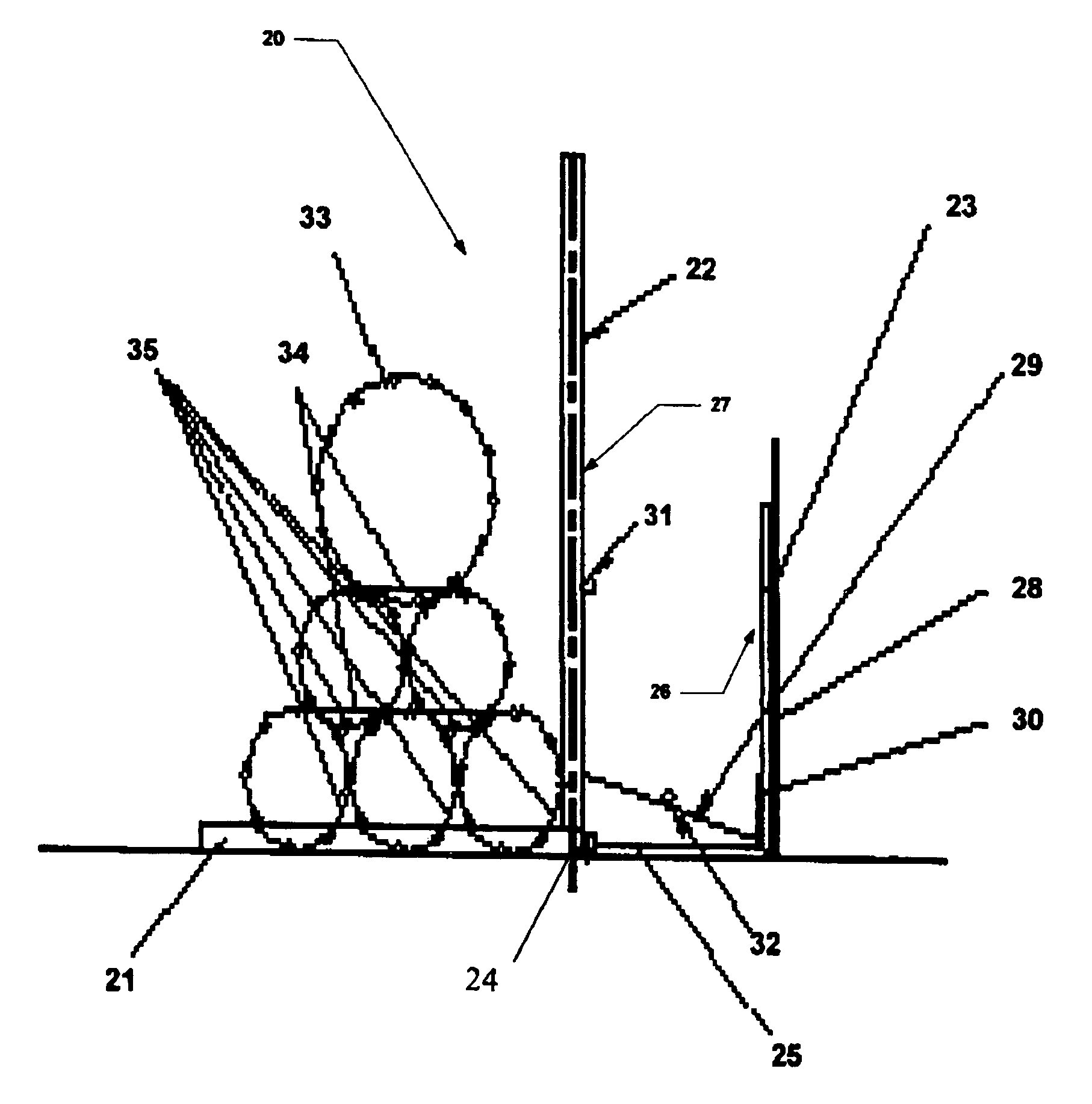
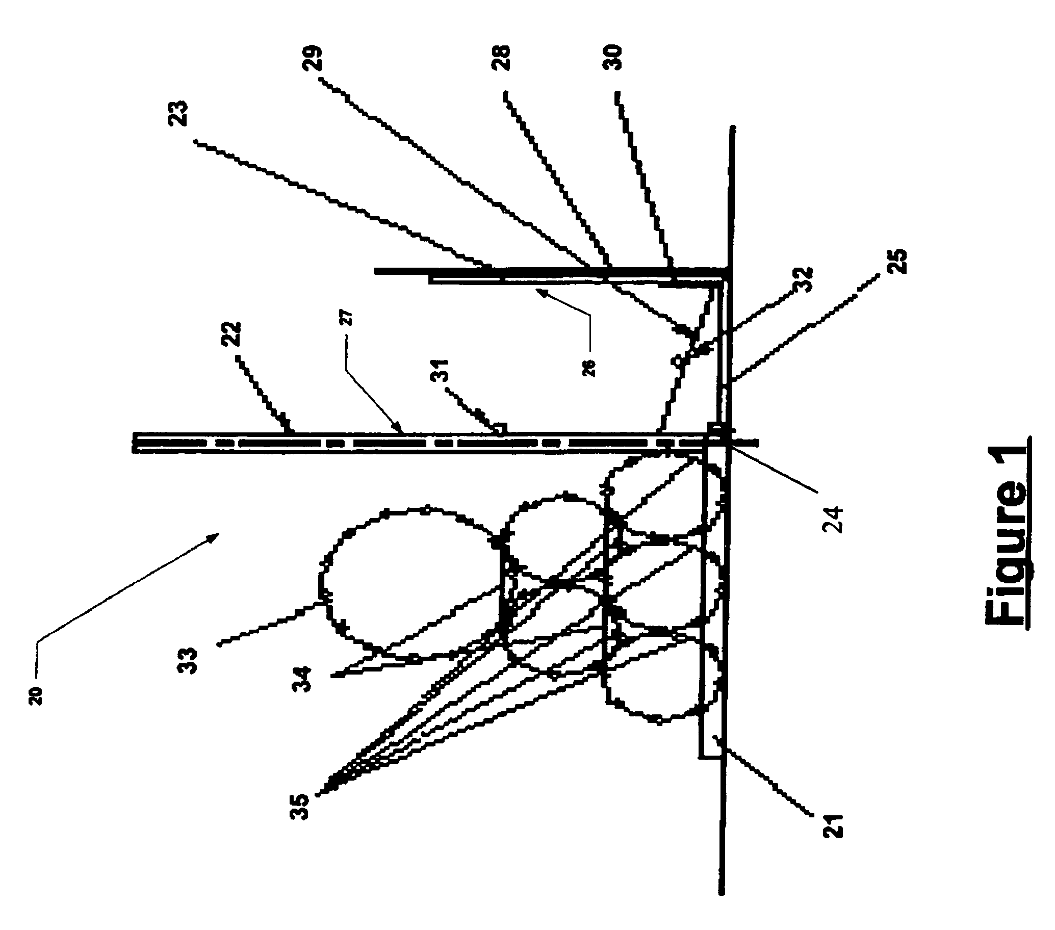
[0017]FIG. 1 illustrates a fence section module 20 of a delay-and-detect system in accordance with the invention. The fence section structural support elemen...


PUM


Abstract

A fence module is adapted for installation without required anchoring buy providing a base frame and a plurality of upright supporting posts extending from the base frame. At least three fence sections extend between the supporting posts. A first fence section at a first extreme end of the fence module, a second fence section at a second extreme end of the fence module, and a third fence section angularly positioned between the first and second fence sections. A pair of vibration sensing modules are used to detect intruders, one applied to the first fence section and a second applied to the third fence section, with the first fence section positioned on the secure end of the protected zone.

Description

FIELD OF THE INVENTION[0001]The present invention relates to perimeter security and more specifically to a security fence module in a delay-and-detect type system.BACKGROUND[0002]Physical barriers in the form of fences are used to surround various facilities ranging from private homes to government installations. One type of fence provides a physical barrier, or delay mechanism, which inhibits a potential intruder from gaining access to a protected zone. Such fences include chain link fences, and razor coil fences. Another type of fence provides both a physical barrier and an alarm, or detection, functionality. Such fences include pressure sensor taut wire fences and rigid fences in combination with vibration sensing modules. This latter type is generally referred to as part of a delay-and-detect type system since the fence provides both a delay and a detect function.[0003]An inherent difficulty with delay-and-detect fences is the need to balance the quality of detection with adequa...

Claims


Application Information

Patent Timeline
Patent Type & Authority Patents(United States)
IPC IPC(8): B21F25/00E04H17/04
CPCE04H17/00
Inventor PERRY, HAIM
Owner SAFEGUARDS TECH
Learn More