
Seat back unit for a chair, in particular for a wheelchair or a stand-up wheelchair

a seat back and chair technology, applied in the field of seat back units for chairs, can solve the problem that the arms of users may glide from the armrests, and achieve the effect of easy operation of the controls and increased or decreased inclination of the seat back

Inactive Publication Date: 2008-09-02
DEGONDA REHAB
View PDF27 Cites 17 Cited by
  • Summary
  • Abstract
  • Description
  • Claims
  • Application Information

AI Technical Summary

Benefits of technology

"The present invention provides a seat back unit that ensures the user's arms are comfortably located in every position, including the horizontal position of the seat back. The unit allows for easy operation of controls and allows for a smooth transfer of the user's body. The seat back frame is tilted around a tilting axis, and the arm rests pivotally attached to the seat back. The unit also includes a stabilizing mechanism that keeps the arm rests in a substantially horizontal position, regardless of the tilting of the seat back. The arm rests are connected to the seat back, so they move downward when the seat back is inclined backward. The seat back unit does not require a support that could interfere with the user's transfer. The actuator for changing the inclination of the seat back frame is connected to the support and to a section of the seat back frame, allowing for easy adjustment of the seat back inclination."

Problems solved by technology

In no position of the seat back there is a danger that the arms of the user may glide from the arm rests.

Method used


Image

  • Seat back unit for a chair, in particular for a wheelchair or a stand-up wheelchair
  • Seat back unit for a chair, in particular for a wheelchair or a stand-up wheelchair
  • Seat back unit for a chair, in particular for a wheelchair or a stand-up wheelchair

Examples


Embodiment Construction

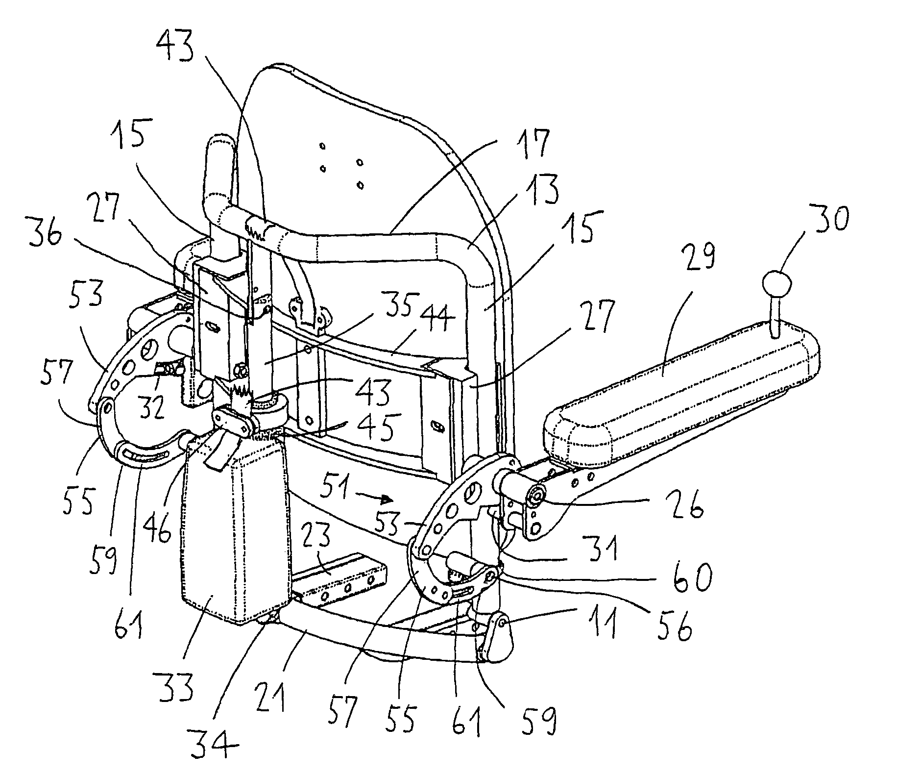
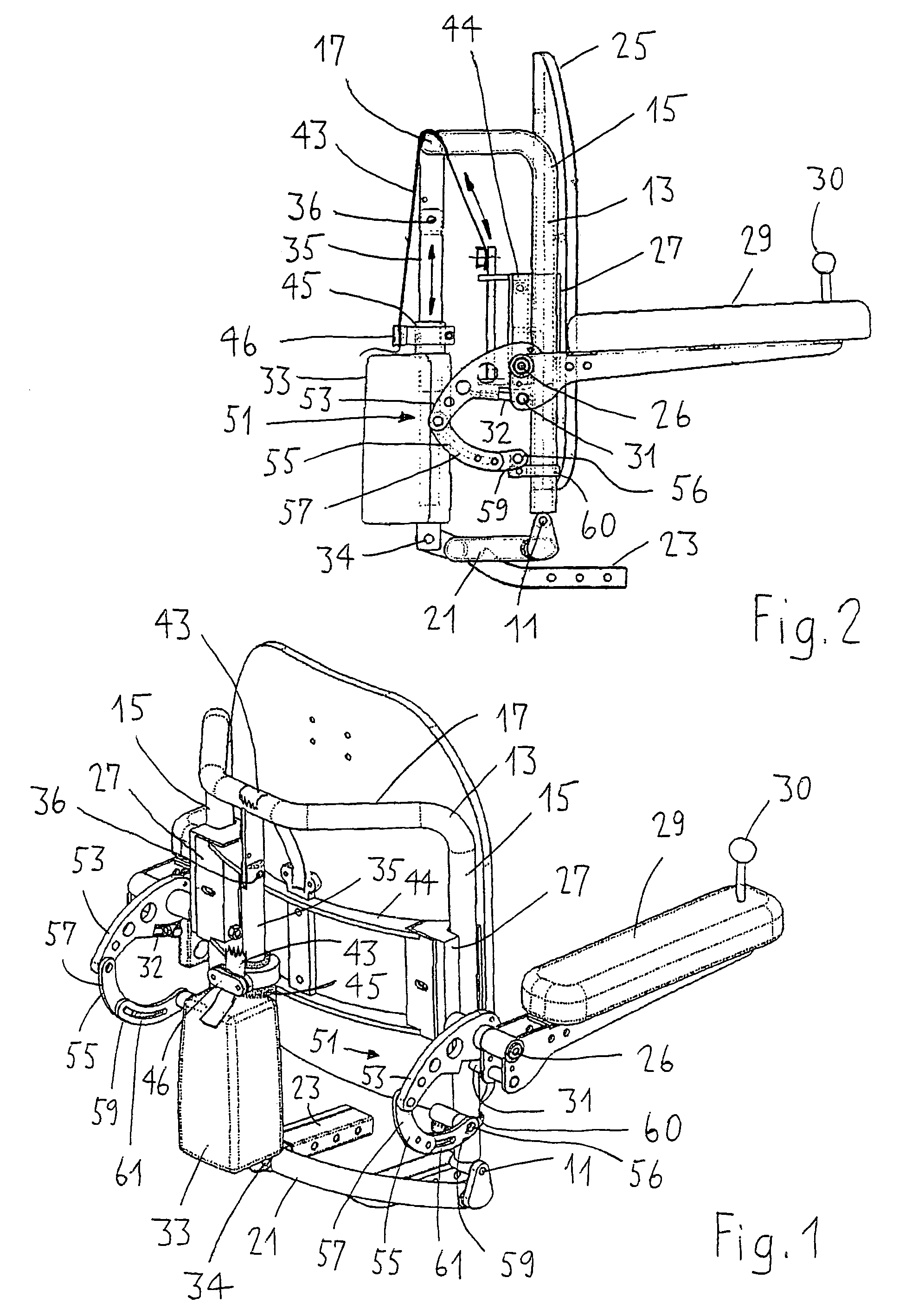
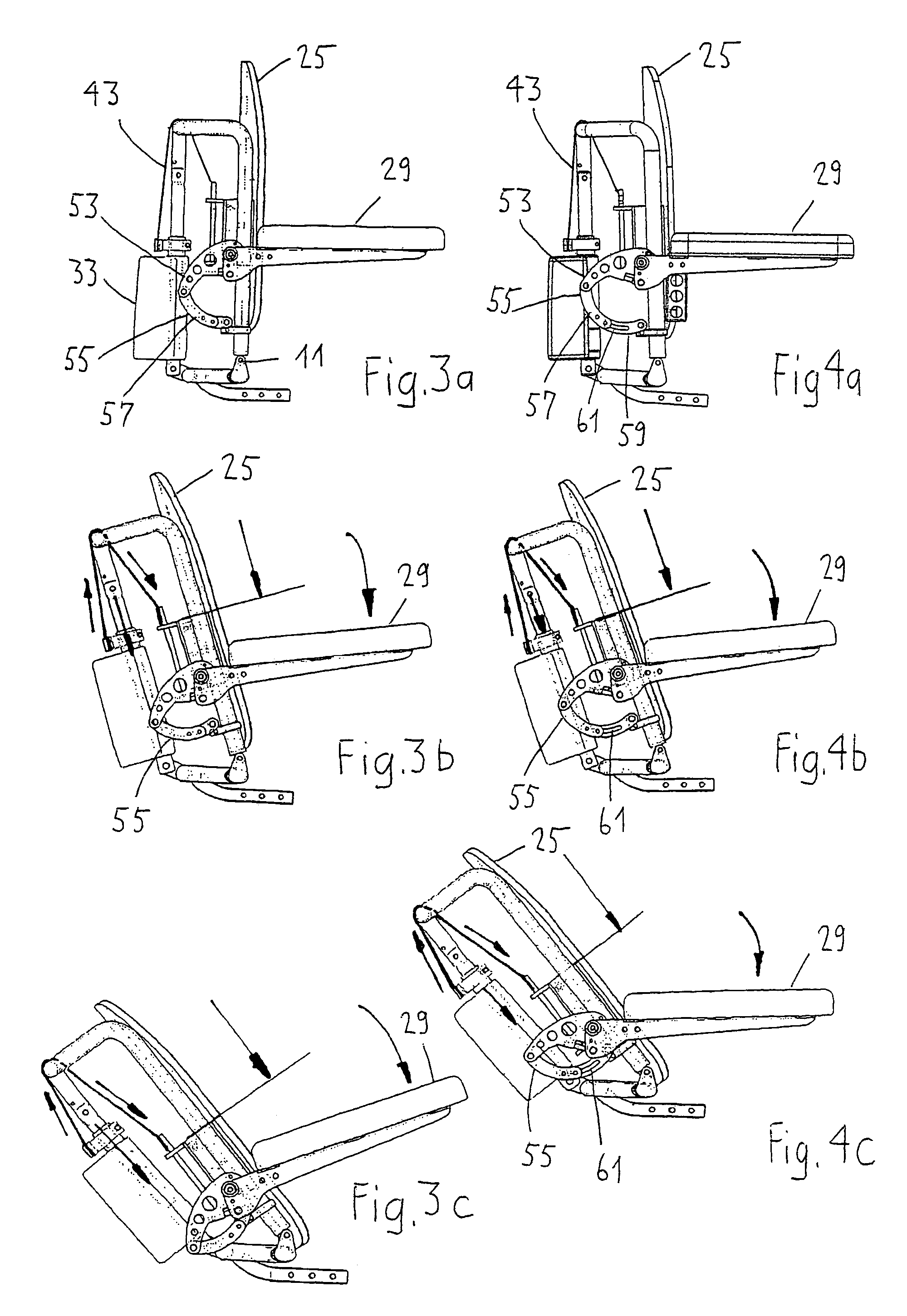
[0015]The seat back unit shown in FIGS. 1 and 2 comprises a seat back frame 13 capable of being tilted around the tilting axis 11. The seat back frame 13 has two columns 15 arranged parallel to each other and being connected by a connecting section 17. Preferably, the seat back frame 13 is made of a single piece of tubing. The columns 15 of the seat back frame 13 are with their lower end connected to the support 21 which has a connector arm 23 for mounting the seat back unit to a chair. However, it would also be possible to connect the seat back frame 13 directly to the chair. The seat back 25 has on each side a guiding portion 27 partly enclosing the pertaining column 15. Accordingly, the seat back 25 is glidingly movable in the seat back frame.

[0016]The arm rests 29 are pivotally connected to the seat back frame 25 at 26. They are kept in the position shown in FIGS. 1 and 2 by an abutment 31. An adjusting screw 32 permits a slight adjustment of the angular position of the arm rest...


PUM


Abstract

The seat back unit has a seat back frame which can be tilted around the tilting axis (11) of the support (21). Movable on the seat back frame (13) is the seat back (25). A linear motor (33) serves to incline the seat back frame (13) together with the seat back (25). With a linear motor (33) the distance between the support (21) and the connecting section (17) of the back frame (13) can be reduced or increased, respectively. A tape (43) extends from a stationary part (45) of the linear motor (33) via the connecting section (17) to the seat back carrier (44). Accordingly, if the seat back frame (13) is tilted towards the rear, the seat back (25) is moved downward together with the arm rests (29) attached to the seat back carrier (44). A stabilizing mechanism (51) keeps the arm rest (29) in a practically horizontal position. Accordingly, on reclining the arms of the user remain always in a practically horizontal position and are finally lowered to a position practically parallel to the body. Therefore there will be never a danger of the arms gliding down from the arm rests (29), so that also a strongly invalid user of the wheelchair will always be in a position to control the control lever (30).

Description

[0001]This application claims priority to Swiss Patent Applocation No. 01628 / 05 filed on Oct. 10, 2005, the entirety of which is incorporated by reference.BACKGROUND OF THE INVENTION[0002]The present invention refers to a seat back unit for a chair, in particular a wheelchair or a stand-up wheelchair.[0003]Chairs on which the seat back can be tilted into lying position are known already for a long time. Many of these chairs have the disadvantage that on tilting of the seat back a relative motion takes place between the back of the user and the seat back causing a so called shirt-pulling effect. In order to avoid this the U.S. Pat. No. 3,630,569 proposes a mechanism which, when the seat back is tilted rearward, moves the seat back also somewhat in direction toward the tilting axis. The chair has an arm rest which is rigidly connected to the seat back. This has the disadvantage that in lying position of the user the arm rest is extending vertically upward.[0004]There exist wheel chair...

Claims


Application Information

Patent Timeline
Patent Type & Authority Patents(United States)
IPC IPC(8): A47C1/024A47C7/54
CPCA61G5/1067A61G5/12A61G5/14A61G2203/74A61G2005/125A61G5/125Y10S297/04
Inventor HUNZIKER, KURT
Owner DEGONDA REHAB
Learn More